4 Power Supply
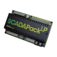
The SCADAPack LP is powered from an 11VDC to 24VDC input power source.
• Input power is applied to the 11-24Vdc positive (+) and negative (-) terminals on connector P3.
Refer to section 14-Specifications of this manual for the minimum and maximum operating voltages
and input power requirements.
• When the input voltage is below the minimum recommended voltage the SCADAPack LP will
turn off.
• Exceeding the maximum input voltage or applying a reverse voltage will blow the input power
fuse.
Note: Unlike the other members of the SCADAPack family, the SCADAPack LP connects only to
DC power sources. Connections to power sources such as 16Vac transformers will blow the
fuse and may cause damage to the SCADAPack LP.
The DC power-input voltage is used to generate 5V for the SCADAPack LP circuitry. The output
capacity of the 5V supply is sufficient to power the SCADAPack LP and a SCADAPack Vision
operator interface with 100mA remaining capacity for a limited number of 5000 Series I/O modules.
For 12VDC power-input voltages a 12V to 24V DC/DC converter is used to power 20mA analog
input and output devices. The DC/DC converter is controlled by the user application program and
may turned on or off. Refer to section 4.2.3-12V to 24V DC/DC Converter Control for more
information on DC/DC converter control.
4.1 System Grounding
In most applications, it is desirable to ground the system by connecting the system power supply
common, to the chassis or panel ground. The negative (–ve) side of the DC power input terminal as
well as all I/O point terminals labeled GND are connected to chassis ground.
4.2 Power Management Features
The SCADAPack LP provides a number of special features to reduce power consumption. These
power management features are:
• COM3 serial port power control.
• VLoop power control.
• 12V to 24V DC/DC Converter Control.
The SCADAPack LP provides three internal digital outputs that can be operated by the user
application to manage the power saving features. Internal digital outputs 9, 10 and 11 and the power
management functions they control are described in the following sections.
Refer to Figure 3: Power Management for an overview of the power management features. Refer
to the appropriate software manual for information on using and controlling the internal Digital
Outputs. For TelePACE applications refer to the Register Assignment for SCADAPack LP I/O
module and for ISaGRAF applications refer to the I/O Complex Equipment for SCADAPack LP I/O.
SCADAPack LP Hardware Manual
May 26, 2006
10

 Loading...