RS-232 COM port (DTE)
8 Pin connector
DTE
5
6
3
4
8
7
1
2
DCD
RxD
TxD
DT
GND
RT
CT
+5V
DCD
RxD
TxD
DTR
GND
RTS
CTS
See devi ce
specification
for pin number
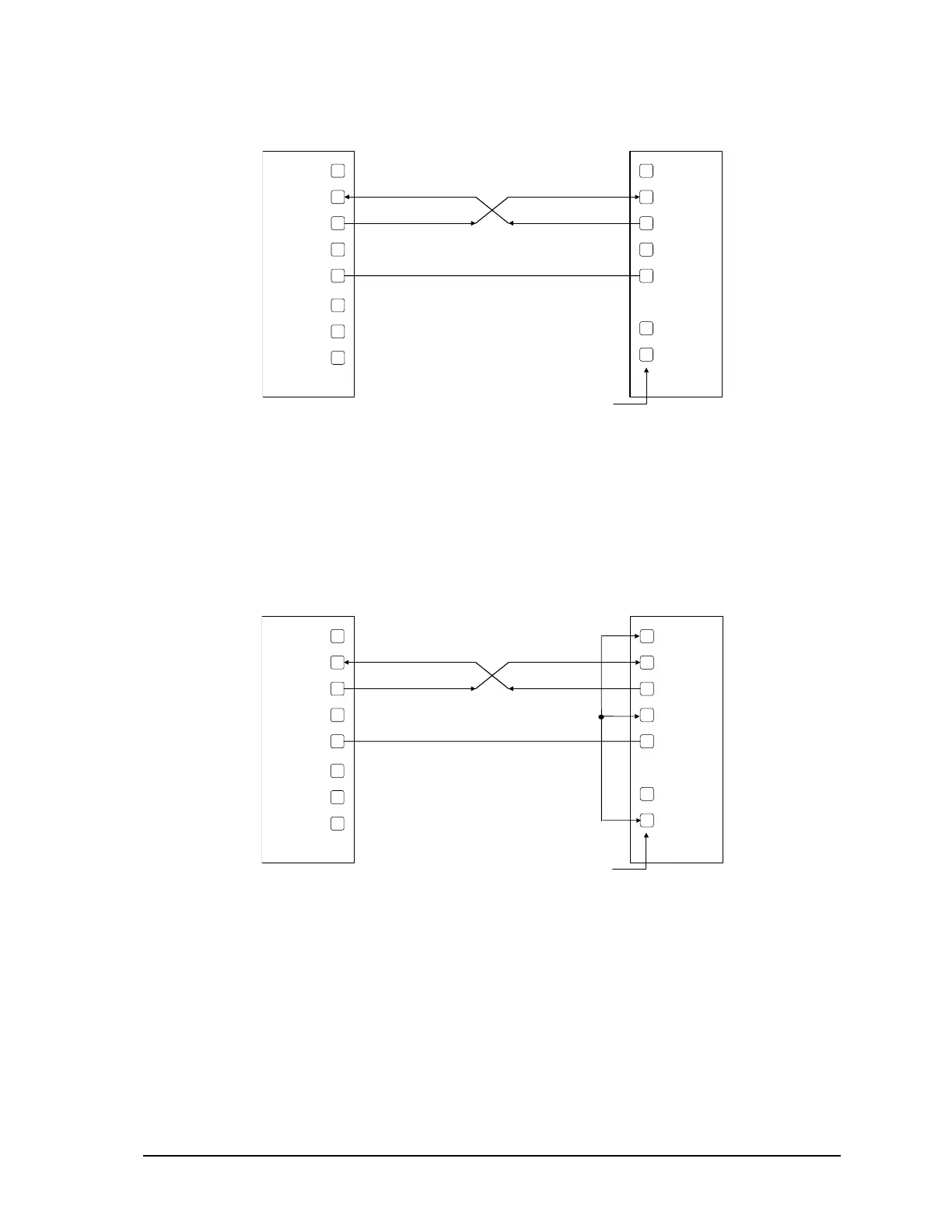
10.2.2 DTE to DTE with Handshaking
Some DTE devices may require hardware handshaking lines. The most common are the CTS and
RTS lines. Less common are the DTR and DCD lines. The controller does not require these lines.
Refer to the specifications of the external device for exact requirements. The following diagram
shows a common connection of an RS-232 COM port with a DTE device requiring handshaking
lines.
RS-232 COM port (DTE)
8 Pin connector
DTE
5
6
3
4
8
7
1
2
DCD
RxD
TxD
DT
GND
RT
CT
+5V
DCD
RxD
TxD
DTR
GND
RTS
CTS
Se e d ev i c
specification
for pin number
10.2.3 DTE to DCE with Handshaking
DCE devices require different wiring. The handshaking lines must be connected in most cases. Note
that many DCE devices are half-duplex. Select half-duplex operation with these devices. The
diagram below shows common connection of a SCADAPack with a DCE device requiring
handshaking lines.
SCADAPack LP Hardware Manual
May 26, 2006
28