9 Counter Inputs
The SCADAPack LP has three counter inputs, identified as Counter 0, 1 and 2. Two of the counter
inputs, Counter 1 and 2, are designed for millivolt level turbine meters. The third, Counter 0, is a
high level digital input for use with open collector/drain output amplifiers.
Refer to the appropriate software manual for information on using the SCADAPack LP Counter
Inputs in application programs.
• For TelePACE applications refer to the Register Assignment for SCADAPack LP I/O module
and
• For ISaGRAF applications refer to the I/O Complex Equipment for SCADAPack LP I/O.
• For C applications use the readCounter function.
9.1 Counter Input 0
Counter Input 0 is used to count contact closures. The input circuitry includes a 1000-ohm resistor
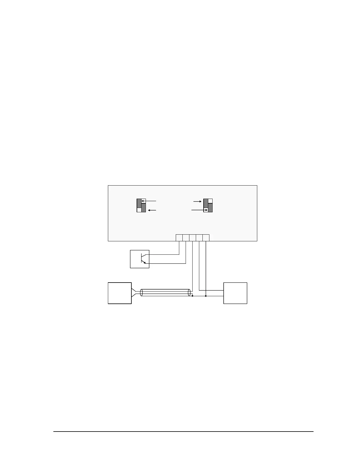
from the counter input to the 5V power supply. Refer to Figure 7: Counter Input Wiring for an
example of wiring to an open collector output.
5 4 3 2 1
0 1 2
P5 – Counters
GND
Turbine
Meter
Sensor
GND
Turbine
Meter
Amplifier
Consult manufacturer of
amplifier for wiring details.
J9 J10 J11 J12
1 2 1 2
Counter 1 input through
internal amplifier
Counter 2 input
bypassing internal amplifier.
Figure 7: Counter Input Wiring
9.2 Turbine Meter Counter Inputs 1 and 2
The SCADAPack LP allows for the direct connection of two turbine meter sensors. These sensors
produce millivolt outputs and do not require an external pre-amplifier when used with the
SCADAPack LP. The turbine meter inputs should be used in low noise environments with shielded
cabling.
There are four jumper links associated with configuring the inputs for either millivolt signals (direct
to sensor) or high level signals such as external amplifiers, dry contacts or open collector outputs.
Refer to Figure 7: Counter Input Wiring for examples of how to configure the jumper links and
wire the inputs. Counter 1 is shown as a millivolt input with a direct connection to a turbine meter
SCADAPack LP Hardware Manual
May 26, 2006
22