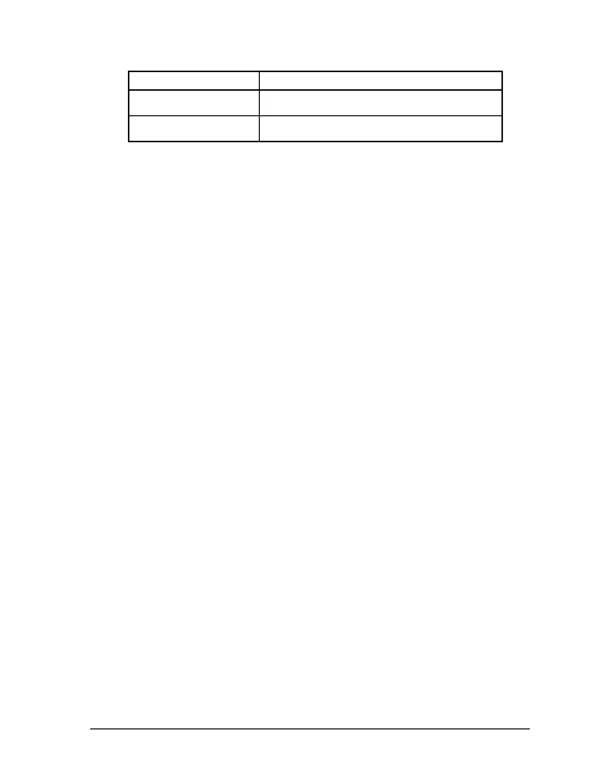
Parameter Supported Values
Protocol
None, Modbus RTU or Modbus ASCII, DF1 or DNP.
Default: Modbus RTU
Addressing Mode
Standard or Extended
Default: Standard
COM1 transmits and receives differential voltages to other RS-485 devices on a network. The RS-
485 specification allows a maximum of 32 devices connected on a single RS-485 network. The
specification for RS-485 recommends that the cable length should not exceed a maximum of 4000
feet or 1200 meters. Termination resistors are required when using long cable lengths and high baud
rates. Refer to section 10.4.2-RS-485 Termination Resistors for information on termination resistors.
The signal grounds of the RS-485 devices in the network are not connected together but instead are
referenced to their respective incoming electrical grounds. The grounds of the RS-485 devices on the
network must be within several volts of each other. The SCADAPack LP ground is connected to the
chassis.
10.4.1 RS-485 Bias Resistors
The RS-485 receiver inputs on the SCADAPack LP controller are biased to ensure that that received
data is driven to a valid state (space) when there are no active drivers on the network. The value of
these bias resistors is 5100 ohms from Ground to the B input and 5100 ohms from +5V to the A
input.
10.4.2 RS-485 Termination Resistors
Termination resistors are required in long networks operating at the highest baud rates. Shorter
networks in high noise environments may also benefit from terminations. Networks as long 1000 ft.
operating at 9600 baud will function without termination resistors. Terminations should be
considered if the baud rate is higher and the network is longer.
When termination resistors are required, they are installed on the first and last station on the RS-485
wire pair. All other stations should not have termination resistors.
RS-485 networks are generally terminated with 120-ohm resistors on each end. The required 120-
ohm resistor must be supplied and installed by the user. When using termination resistors it is
necessary to increase the line biasing by adding lower value bias resistors in order to generate at least
0.2V across RS-485 line. The suggested value of the bias resistors is 470 ohms. One bias resistor is
installed from P5 terminal 7 (B) to P5 terminal 8 (COM). The second bias resistor is installed from
P5 terminal 6 (A) to +5V. +5V is available on P7 pin 1 when J13 is installed.
10.5 RS-485 Wiring Examples
A typical RS-485 wiring example is shown below. COM1 is shown connected to a multivariable
transmitter such as the Rosemount 3095. The power for the transmitter can come from the
SCADAPack LP power input source or can be obtained from the 24V Vloop output for possible
power savings.
SCADAPack LP Hardware Manual
May 26, 2006
31