7 Digital Outputs
The SCADAPack LP I/O Module provides eight universal digital inputs or outputs. Outputs are
open-collector/open drain type for use with sustained DC loads up to 1 ampere. Higher peak loads
can be tolerated.
The negative side of the load is connected to the desired terminal on the controller terminal block P3.
The positive side of the load connects to a power supply. When the load is on the load current is
switched through the controller to terminal labeled GND. GND must be connected to the negative
side of the power supply.
Inductive load transient suppression is built into each digital output point. It is not necessary to add
additional inductive load transient suppression unless highly inductive loads (greater than 1H) are
operated continuously at greater than 0.5Hz.
The SCADAPack LP also provides three internal digital outputs that can be controlled by the user
application to manage power saving features unique to the SCADAPack LP.
Refer to the appropriate software manual for information on using the SCADAPack LP Digital
Inputs and Outputs in application programs. For TelePACE applications refer to the Register
Assignment for SCADAPack LP I/O module and for ISaGRAF applications refer to the I/O Complex
Equipment for SCADAPack LP I/O.
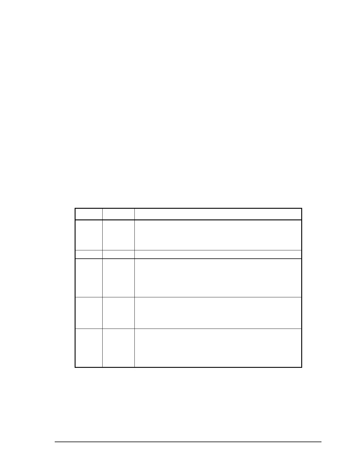
The following table describes the SCADAPack LP digital outputs.
Output Type Description
0 to 7 external Open drain outputs. These outputs are located on terminal
P3.
0 = output transistor off
1 = output transistor on
8 internal Not used for applications, internal use only.
9 internal com3 (HMI) power control
0 = off
1 = on
See section 4.2.1-COM3 Serial Port Power Control for
details.
10 internal VLOOP power control
0 = off
1 = on
See section 4.2.2- VLOOP Power Control for details.
11 internal DC/DC converter control
0 = off
1 = on
See section 4.2.3-12V to 24V DC/DC Converter Control for
details.
SCADAPack LP Hardware Manual
May 26, 2006
19