Input Type Description
detect incorrect outputs. A point is compared if it has been
turned on at any time since controller reset. This input
indicates if one or more outputs mismatch. The source of the
mismatch can be determined by comparing each digital input
against the corresponding digital output.
0 = off
1 = on
14 internal If the SCADAPack Vision power key is pressed while DO 9
is off, digital input bit 14 will be set. DI 14 is cleared 5
minutes after the power key is pressed or immediately upon
DO 9 turning on.
See section 4.2.1-COM3 Serial Port Power Control for
details.
15 internal reserved for future use
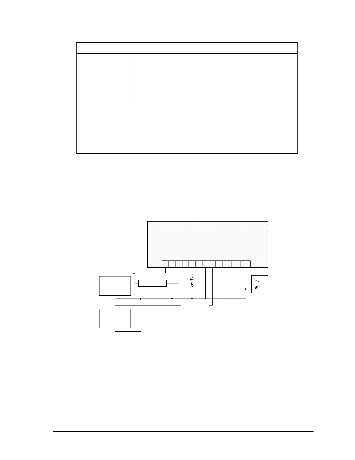
8.1 Digital I/O Connection Examples
Various I/O point wiring examples are shown in Figure 6: Digital Input/Output Wiring. Digital I/O
point 0 is shown connected to a 12V load that uses the same 12V power supply that powers the
SCADAPack LP. Digital I/O point 4 is shown connected to a 24V load and external 24V-power
supply. Digital I/O point 2 is shown monitoring a dry contact. Digital I/O point 5 is shown
monitoring an open collector contact. Transient voltage suppression is included on each I/O point.
109876543
GND0123 45
P3 – DC Power In and Digital I/O
+ 24V Load –
1 2
+–
11 12
67GND
+
12Vdc Power
Supply
_
+
24Vdc Power
Supply
_
+ 12V Load –
Figure 6: Digital Input/Output Wiring
SCADAPack LP Hardware Manual
May 26, 2006
21