+
External 24Vdc
Power Supply
_
Voltage
8
+
_
Vloop
7 6 5 4 3 2 1
GND012345
12304
Current
P10 - Analog Inputs
+
_
PWR
Voltage O/P
COM
PWR
Current O/P
COM
J1 J2 J3 J4 J5
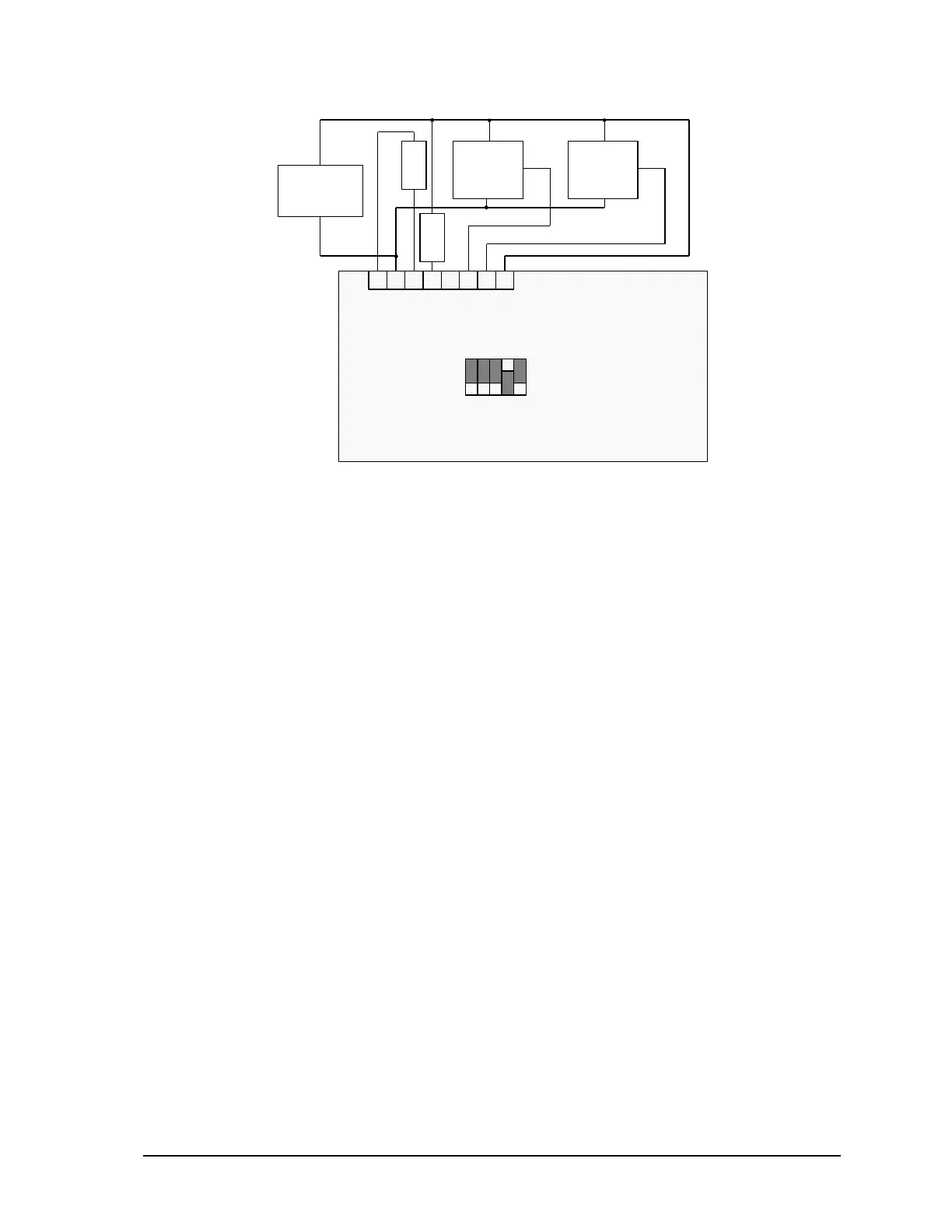
Figure 4: Analog Input Wiring
5.3 Analog Input Range Jumpers
Channels 0 through 4 can be user configured for either voltage or current operation with jumper
links. Refer to Figure 4: Analog Input Wiring for examples of the how a jumper link is installed on
J1 through J5. A jumper link installed in the Current position of the header results in a 250Ω resistor
across the appropriate analog input. A jumper link installed in the Voltage position of the header
results in high impedance analog input.
5.4 Analog Inputs Data Format
The I/O analog inputs have a 16-bit, unipolar, analog to digital (A/D) converter that measures input
voltages from 0 to 10V. The analog inputs are factory calibrated to scale the data and represent it
with a 15 bit unsigned number.
When an analog input is configured for voltage, 10V input is represented with 15 bits of data. The
input resolution is 0.305mV/count.
When an analog input is configured for current, 20mA input is represented with 14 bits of data.
There is 100% over range. The input resolution is 1.22µA/count.
The channel 5 analog input is configured for voltage. 32.768V is represented with 15 bits of data.
The input resolution is 0.001V/count.
SCADAPack LP Hardware Manual
May 26, 2006
15