J5
Analog Input 4 Range Figure 4: Analog Input Wiring
J8
J9
Counter Input 1 Type Figure 7: Counter Input Wiring
J10
Counter Input 2 Type Figure 7: Counter Input Wiring
J11
Counter Input 1 Type Figure 7: Counter Input Wiring
J12
Counter Input 2 Type Figure 7: Counter Input Wiring
J13
COM2 5 Volts on Pin 1 10.1.1-
COM2 RS-232 Serial Port
11.5 Status LED
The STAT LED indicates an alarm condition. The STAT LED blinks when an alarm occurs. The
STAT LED turns off when all alarms clear.
The STAT LED blinks a binary sequence indicating alarm codes. The sequences consist of long and
short flashes, followed by an off delay of 1 second. The sequence then repeats. The sequence may be
read as the Controller Status Code. A short flash indicates a binary zero. A long flash indicates a
binary one. The least significant bit is output first. As few bits as possible are displayed, all leading
zeros are ignored. The application program defines the values of the alarm codes.
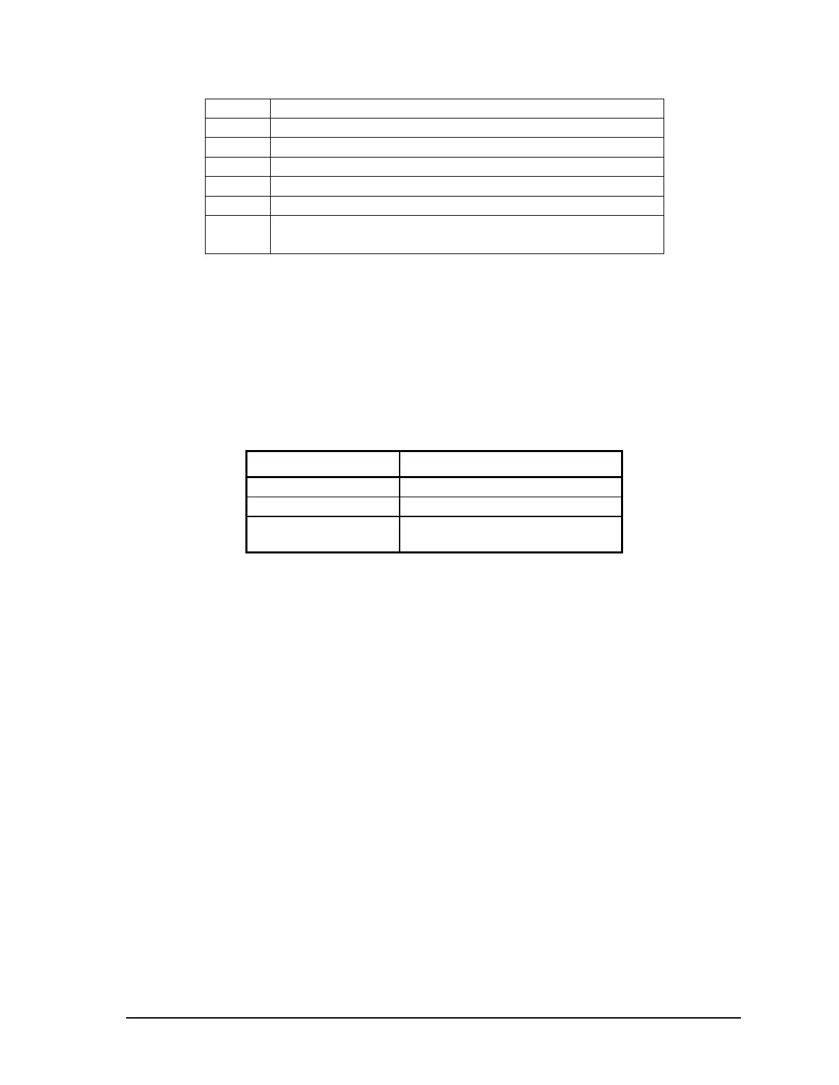
The table below shows the meaning of the sequences.
Sequence CONTROLLER STATUS CODE
Off 0 = Normal
1 Long I/O Module Error Indication
1 Short, 1 Long Register Assignment Checksum
Error
11.5.1 I/O Module Error Indication
When the Status LED flashes the controller status code 1 (i.e. a long flash, once every second), there
is a communication failure with one or more I/O module. To correct the problem, do one of the
following:
1. Ensure that every module contained in the Register Assignment Table is connected to the
controller. Check that the module address selected for each module agrees with the selection
made in the Register Assignment Table.
2. If a module is still suspect of having failed, confirm the failure by removing the module from the
Register Assignment Table. Download the changes to the controller. The Status LED should stop
flashing.
3. If a module is currently not connected to the controller, delete it from the Register Assignment
Table. Download the changes to the controller. The Status LED should stop flashing.
4. If unused modules must be intentionally left in the Register Assignment Table, the I/O error
indication may be disabled from a selection box on the Register Assignment dialog.
11.5.2 Register Assignment Checksum Error
When the status LED flashes the controller status code 2 (i.e. a short flash then a long flash followed
by a 1 second of delay), this indicates the register assignment is not valid. To correct this problem,
initialize the register assignment from the TelePACE software, or alternatively, perform a COLD
BOOT as described in section 11.1.3-Cold Boot Mode of this manual. The status LED should stop
flashing.
SCADAPack LP Hardware Manual
May 26, 2006
36