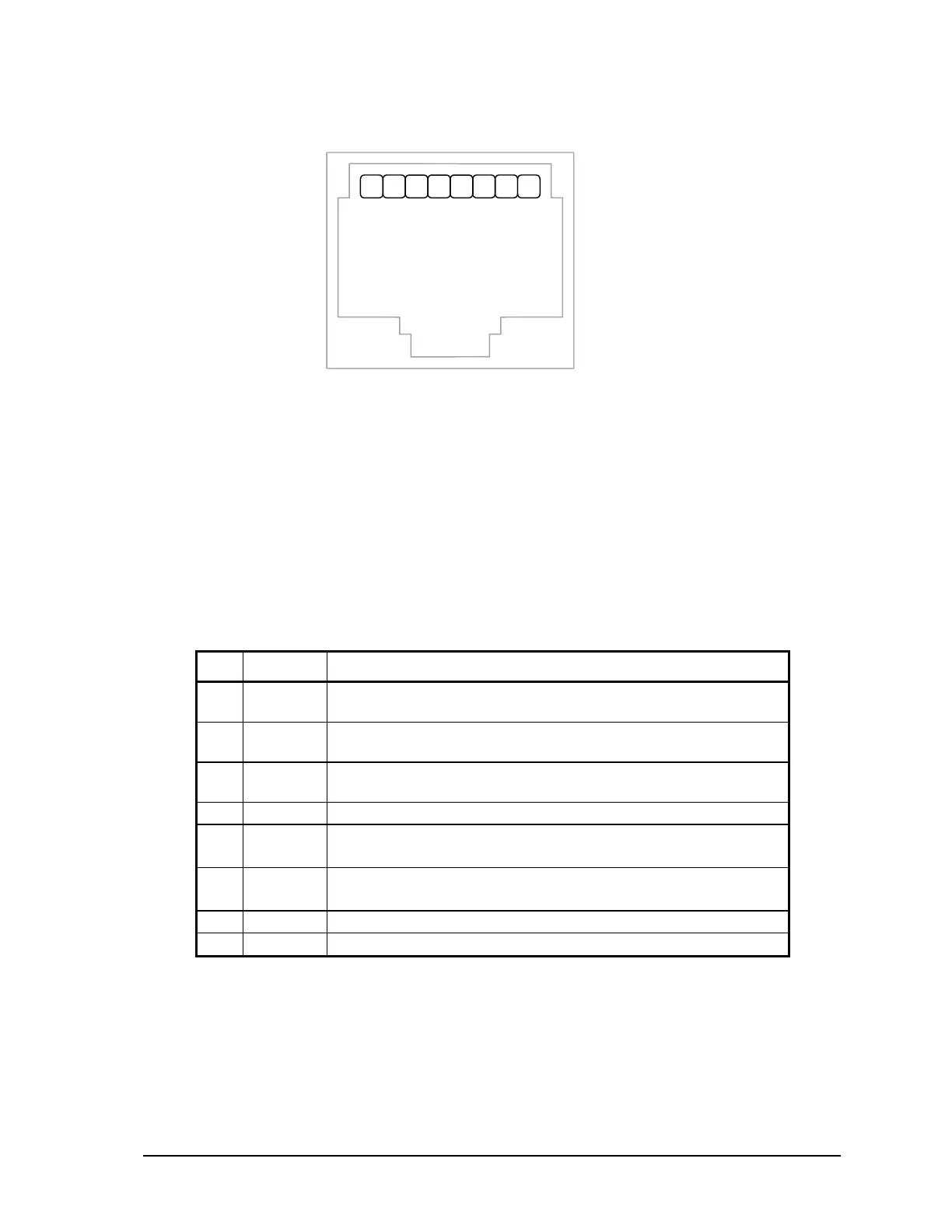
RJ-45 Modular Jack
1.
+5V
2.
Test1
3.
Test2
4.
GND
5.
RxD
6.
TxD
7.
NC
8.
NC
2
1
8
7
6
5
4
3
NOTES:
• +5V is available on Pin 1 when turned on by the user under program control, when the
SCADAPack LP detects the contact closure of the ON switch of the SCADAPack Vision or
when the LED Power is ON.
• The SCADAPack Vision ON switch is wired to Pins 2 and 3. It is important that when a
SCADAPack Vision is not used that only the TxD, RxD and GND pins are used.
• The low power transmitters used in COM3 generate 0 to 5V levels. This is less than the RS-232
specification but still compatible with all RS-232 receivers. Cables should be limited to a
maximum of 10 ft (3m).
The following table provides a description of the function of each pin of the RJ-45 connector. In this
table a MARK level is a voltage of +3V or greater and a SPACE level is a voltage of 0V.
Pin Function Description
1 5V
(Output)
+5V power for the SCADAPack Vision.
2 Test1
(Input)
Used to detect SCADAPack Vision ON switch closure.
3 Test2
(Output)
Used to detect SCADAPack Vision ON switch closure.
4 GND This pin is connected to the system ground.
5 RxD
(Input)
The level is SPACE on standby and MARK for received data.
The LED is lit for a MARK level.
6 TxD
(Output)
The level is SPACE on standby and MARK for transmitted data.
The LED is lit for a MARK level.
7 NC No connection.
8 NC No connection.
10.2 RS-232 Wiring Examples
10.2.1 DTE to DTE without Handshaking
There are several methods for wiring the RS-232 COM port to DTE (Data Terminal Equipment) and
DCE (Data Communications Equipment) devices. The simplest connection requires only 3 wires:
RxD, TxD and signal ground. The following diagram shows a common RS-232 COM port to DTE
device.
SCADAPack LP Hardware Manual
May 26, 2006
27