6 Analog Outputs
The SCADAPack LP may include two channels of analog output if this option was requested at time
of purchase.
Refer to the appropriate software manual for information on using the SCADAPack LP Analog
Outputs in application programs. For TelePACE applications refer to the Register Assignment for
SCADAPack LP I/O module and for ISaGRAF applications refer to the I/O Complex Equipment for
SCADAPack LP I/O.
6.1 Current Outputs
The optional analog output module provides two 20mA analog outputs.
The internal power supply powers the analog output circuits. The user can, under program control,
boost the DC Input Power to 24V. This is required when generating current outputs into high
resistance loads. Refer to section 4.2.3-12V to 24V DC/DC Converter Control for further
information.
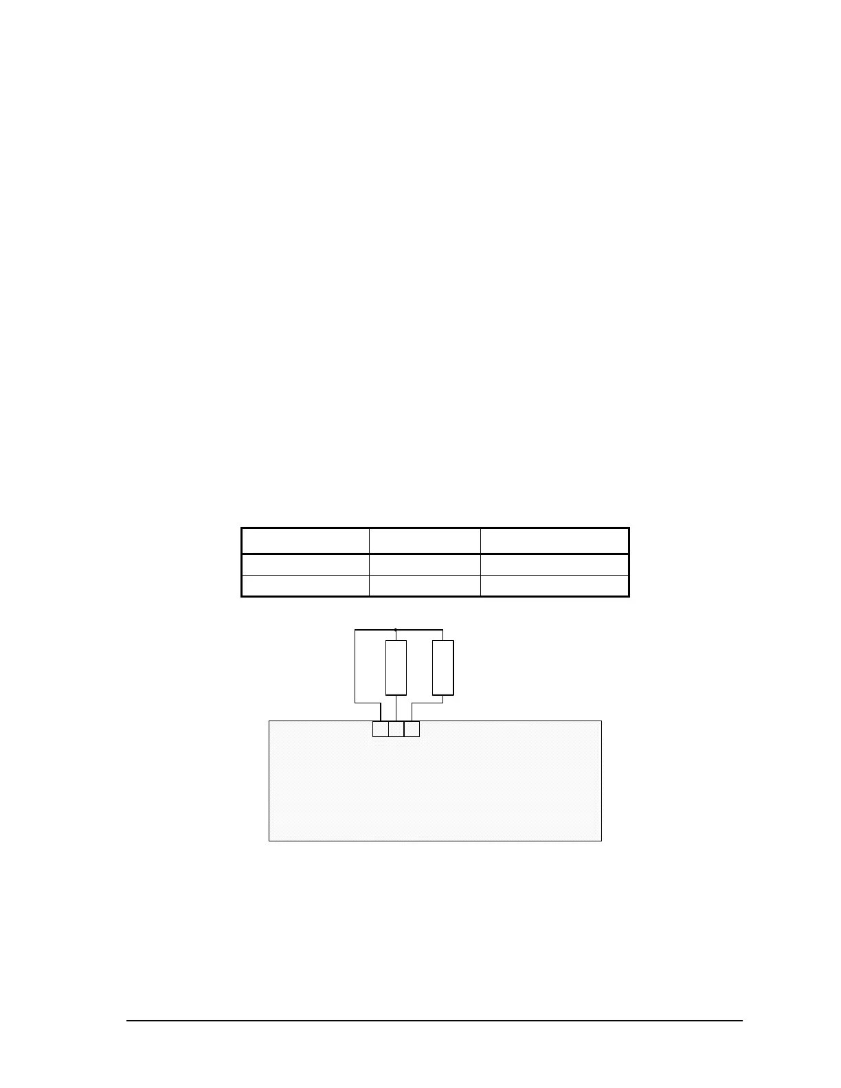
Figure 5: Analog Output Wiring shows example wiring of the analog outputs.
6.2 Voltage Outputs
To obtain voltage outputs, connect a load resistor in the current output. Connect the voltage device
across the load resistor. The table below list resistance values and output range settings for two
common voltage ranges. The resistance value listed is the parallel resistance of the device and the
load resistor.
Voltage Range Resistance Output Range
0 to 5V
250Ω
0-20mA
0 to 10V
500Ω
0-20mA
3 2 1
GND 0 1
P10 - Analog Outputs
L
O
A
D
+
L
O
A
D
+
Figure 5: Analog Output Wiring
6.3 Analog Outputs Data Format
The optional analog output module has a 12-bit, unipolar, digital to analog converter. There are 4096
counts in the output signal range. The 0-20mA output range resolution is 4.88µA/count. The table
below shows the output current for several D/A values.
SCADAPack LP Hardware Manual
May 26, 2006
17