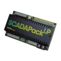
Why is the LED dim on my Control Microsystems Controller?
- AAlicia PottsSep 13, 2025
This is normal operation for your Control Microsystems Controller when it is in low power mode or sleep mode.

 Loading...
Why is the LED dim on my Control Microsystems Controller?
This is normal operation for your Control Microsystems Controller when it is in low power mode or sleep mode.
| Model | SCADAPack LP |
|---|---|
| Digital Inputs | 8 |
| Analog Inputs | 4 |
| Analog Outputs | 2 |
| Communication Protocols | Modbus RTU, Modbus TCP, DNP3 |
| Enclosure Rating | IP20 |
| Certifications | CE, UL, CSA |
| Type | Programmable Logic Controller |
| Processor | 32-bit |
| Memory | 4 MB Flash |
| Power Supply | 10-30 VDC |
| Digital Outputs | 4 |
| Communication Ports | RS-232, RS-485 |
| Operating Temperature | -40 to 70°C |
Explains how to connect field wires to SCADAPack controllers using screw terminals.
Describes connecting the system power supply common to chassis or panel ground.
Details features like COM3 port power, VLoop, and DC/DC converter control.
Explains controlling power to the COM3 serial port for HMI communication.
Describes controlling the VLOOP output for powering analog input loops.
Details controlling the DC/DC converter for VLOOP and analog output modules.
Covers ambient temperature and lithium battery voltage monitoring.
Discusses external analog inputs, their configuration, and wiring.
Details how to connect the six external analog inputs to connector P10.
Explains wiring for loop-powered and self-powered transmitters.
Describes using jumper links to configure voltage or current inputs.
Explains the A/D converter resolution and data format for inputs.
Describes the two optional 20mA analog outputs and power boosting.
Explains how to obtain voltage outputs by connecting a load resistor.
Details the 12-bit DAC resolution and output signal range.
Details using Counter Input 0 for counting contact closures.
Describes connecting millivolt-level turbine meter sensors to inputs 1 and 2.
Overview of RS-232 ports COM2 and COM3, including wiring requirements.
Lists serial and protocol parameters and default values for COM2.
Lists serial and protocol parameters for COM3, intended for SCADAPack Vision.
Provides wiring diagrams for DTE/DCE connections with and without handshaking.
Shows a simple 3-wire connection between two DTE devices.
Illustrates DTE to DTE connection with common handshaking lines (CTS/RTS).
Depicts a connection between a SCADAPack and a DCE device requiring handshaking.
Details cables for connecting RJ-45 ports to DE-9 connectors.
Describes the cable for connecting SCADAPack RJ-45 to a PC's DE-9P DTE.
Details the cable for connecting SCADAPack RJ-45 to a SCADAPack Vision DE-9P.
Explains the cable for connecting SCADAPack RJ-45 to a DCE device's DE-9S.
Describes the RS-485 port, its parameters, and network specifications.
Explains the function and value of RS-485 bias resistors.
Details when and how to install RS-485 termination resistors.
Provides an example of RS-485 wiring to a multivariable transmitter.
Explains different startup modes: RUN, SERVICE, and COLD BOOT.
Describes the normal operating mode where application programs execute.
Details mode for programming and maintenance, allowing reprogramming.
Explains mode for firmware installation, initializes controller and erases programs.
Describes extremely low power operation and conditions for waking up.
Lists the 23 LEDs on the SCADAPack LP and their functions.
Explains how to disable LEDs to conserve power using the LED POWER button.
Lists configurable jumpers and their relevant sections in the manual.
Describes the STAT LED's function indicating alarm conditions.
Explains how the STAT LED indicates communication failures with I/O modules.
Details how the STAT LED indicates an invalid register assignment.
Describes the power supply fuse and replacement procedure.
Explains the battery's role in maintaining CMOS memory and real-time clock.
Provides step-by-step instructions for replacing the lithium battery.
Lists common problems and actions for analog input issues.
Lists common problems and actions for analog output issues.
Lists common problems and actions for digital input issues.
Lists common problems and actions for digital output issues.
Lists common problems and actions for counter input issues.
Covers general specifications like I/O terminations, dimensions, and environment.
Details controller specifications like processors, memory, and clock.
Lists specifications for COM1 (RS-485) and COM2 (RS-232) ports.
Describes the LEDs for COM ports, Status, I/O, Counters, and Push-button.
Specifies DC power input requirements and turn-on/off voltages.
Details expansion capabilities with 5000 Series I/O modules.
Lists specifications for analog input points, resolution, and resistance.
Details specifications for analog output points, range, resistance, and accuracy.
Lists specifications for digital counter inputs and turbine meter inputs.
Covers specifications for digital I/O points, rating, and input thresholds.