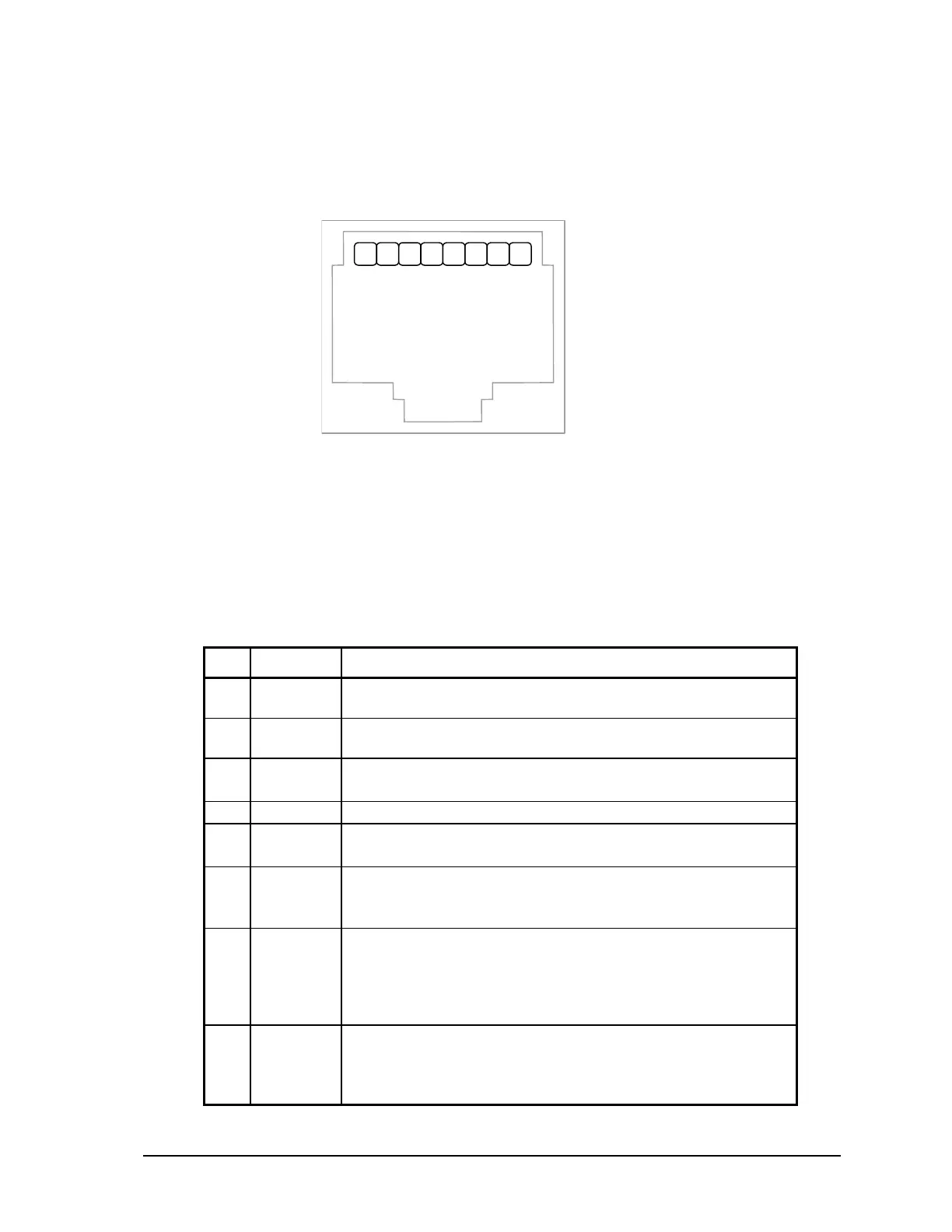
Connections to COM2 are made through a RJ-45 modular connector. COM2 supports six signals
plus Ground and 5V power. The following diagram shows the pin connections for the RS-232 (RJ-
45) port connector for COM2.
RJ-45 Modular Jack
1.
+5V
2.
DCD
3.
DTR
4.
GND
5.
RxD
6.
TxD
7.
CTS
8.
RTS
2
1
8
7
6
5
4
3
NOTES:
• +5V is only available on Pin 1 when a jumper is installed on J13. Refer to the Figure 2:
SCADAPack LP Board Layout for the location of J13.
• The low power transmitters used in COM2 generate 0 to 5V levels. This is less than the RS-232
specification but still compatible with all RS-232 receivers. Cables should be limited to a
maximum of 10 ft (3m).
The following table provides a description of the function of each pin of the RJ-45 connector. In this
table a MARK level is a voltage of +3V or greater and a SPACE level is a voltage of 0V.
Pin Function Description
1 5V
(Output)
This pin can be connected to the 5V power supply by installing
a jumper at J13 on the SCADAPack LP.
2 DCD
(Input)
The DCD led is on for a MARK level.
3 DTR
(Output)
This pin is normally at a MARK level.
This pin is at a SPACE level when DTR is de-asserted.
4 GND This pin is connected to the system ground.
5 RxD
(Input)
The level is SPACE on standby and MARK for received data.
The LED is lit for a MARK level.
6 TxD
(Output)
The level is SPACE on standby and MARK for transmitted
data.
The LED is lit for a MARK level.
7 CTS
(Input)
This level must be a MARK for the communication port to
transmit data. When the attached device does not provide this
signal, the controller keeps the line at a MARK.
When the attached device does provide this signal, it must set
CTS to MARK to allow the controller to transmit data.
8 RTS
(Output)
This pin is a MARK if full-duplex operation is selected for the
port.
This pin is set to a MARK just before and during transmission
of data if half-duplex operation is selected.
SCADAPack LP Hardware Manual
May 26, 2006
25