Safety
Information
Product
Information
Mechanical
Installation
Electrical
Installation
Keypad and
Display
Parameters
Quick Start
Commissioning
Diagnostics Options Parameter List
UL Listing
Information
16 Commander SK Size 2 to 6 Getting Started Guide
www.controltechniques.com Issue Number: 2
3 Mechanical Installation
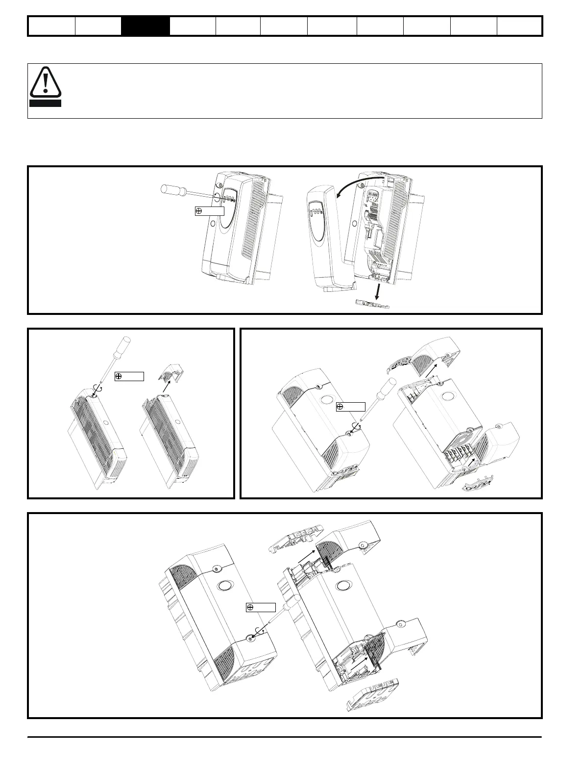
3.1 Removing the terminal covers
To remove a terminal cover, undo the screw and lift the terminal cover off as shown. When replacing the terminal covers, the screws should be
tightened with a maximum torque of 0.8Nm (0.6 lb ft) for the control terminal cover and 1Nm (0.7 Ib ft) for the other covers.
The drive is intended to be mounted in an enclosure which prevents access except by trained and authorised personnel, and which
prevents the ingress of contamination. It is designed for use in an environment classified as pollution degree 2 in accordance with IEC
60664-1. This means that only dry, non-conducting contamination is acceptable.
Figure 3-1 Removing the control stage terminal cover
Figure 3-2 Removing the size 2 power stage terminal cover
Figure 3-3 Removing the size 3 power stage terminal cover
Figure 3-4 Removing the size 4 power stage terminal cover
WARNING
Pozi Pz1
Pozi Pz2
Pozi Pz2
Pozi Pz2