Safety
Information
Product
Information
Mechanical
Installation
Electrical
Installation
Keypad and
Display
Parameters
Quick Start
Commissioning
Diagnostics Options Parameter List
UL Listing
Information
32 Commander SK Size 2 to 6 Getting Started Guide
www.controltechniques.com Issue Number: 2
4.3 Ground leakage
The ground leakage current depends upon the internal EMC filter being
fitted. The drive is supplied with the filter fitted. Instructions on removal
of the internal EMC filter are given in section 4.4.2 Internal EMC filter on
page 33.
With internal EMC filter fitted
10µA DC (10MΩ internal bleed resistor, relevant where DC leakage
current is being measured)
28mA AC at 400V, 59Hz (proportional to supply voltage and
frequency).
The above leakage currents are just the leakage currents of the drive
with the internal EMC filter connected and do not take into account any
leakage currents of the motor or motor cables.
With internal EMC filter removed
<1mA
In both cases, there is an internal voltage surge protection device
connected to ground. Under normal circumstances this carries
negligible current.
4.4 EMC (Electromagnetic compatibility)
4.4.1 Grounding hardware
The Commander SK size 2 and 3 are provided with a grounding bracket
and grounding clamp. They can be used as cable management bracket/
clamp or they can be used to facilitate EMC compliance. They provide a
convenient method for direct grounding of cable shields without the use
of 'pig tails'. Cable shields can be bared and clamped to the grounding
bracket using metal clips or clamps* (not supplied) or cable ties. Note
that the shield must in all cases be continued through the cable clamp to
the intended terminal on the drive, in accordance with the connection
details for the specific signal.
*A suitable clamp is the Phoenix DIN rail mounted SK14 cable clamp (for
cables with a maximum outer diameter of 14mm).
Figure 4-9 Fitting the grounding clamp
A faston tab is located on the grounding bracket for the purpose of
connecting the drive 0V to ground should the user require to do so.
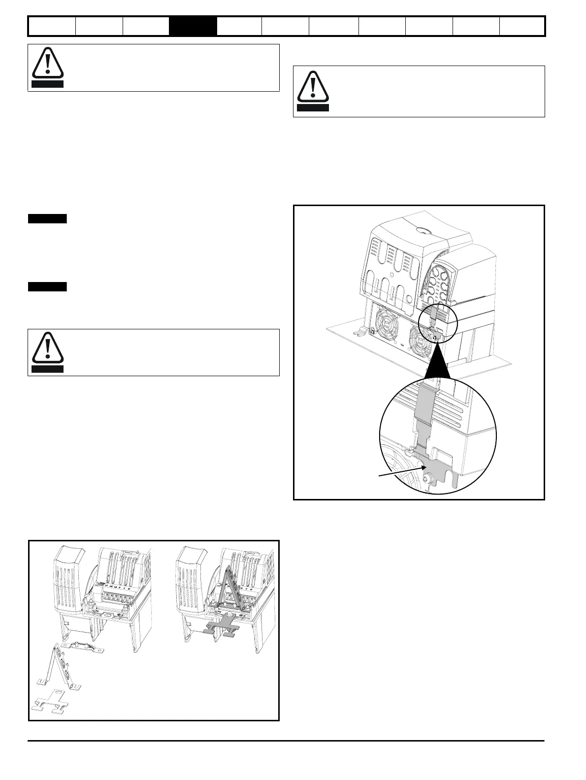
When a Commander SK size 4 or 5 is through-panel mounted, the
grounding link bracket must be folded upwards. A screw can be used to
secure the bracket or it can be located under the mounting bracket to
ensure that a good ground connection is made. This is required to
provide a grounding point for the grounding bracket as shown in Figure
4-9.
Figure 4-10 Grounding link bracket in its surface mount position
(as supplied)
The drive must be grounded by a conductor sufficient to carry
the prospective fault current in the event of a fault. See also
the warning in section 4.3 Ground leakage relating to ground
leakage current.
When the internal EMC filter is fitted, the leakage current is
high. In this case, a permanent fixed ground connection must
be provided, or suitable measures taken to prevent a safety
hazard occurring if the connection is lost.
WARNING
NOTE
NOTE
WARNING
On Commander SK size 2, the grounding bracket is secured
using the power ground terminal of the drive. Ensure that the
supply ground connection is secure after fitting/removing the
grounding bracket. Failure to do so will result in the drive not
being grounded.
WARNING
Grounding
link bracket