Safety
Information
Product
Information
Mechanical
Installation
Electrical
Installation
Keypad and
Display
Parameters
Quick Start
Commissioning
Diagnostics Options Parameter List
UL Listing
Information
Commander SK Size 2 to 6 Getting Started Guide 29
Issue Number: 2 www.controltechniques.com
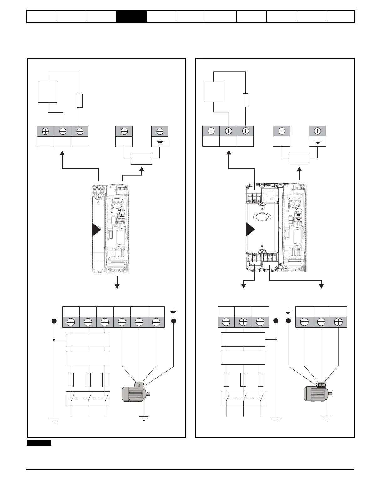
4 Electrical Installation
4.1 Power connections
4.1.1 AC and DC connections
Figure 4-1 Size 2 power connections
An optional internal braking resistor is available for Commander SK size 2.
For further information, see the Commander SK Technical Data Guide.
Figure 4-2 Size 3 power connections
L1 L2
L2L1 L3 U V W
Optional RFI
filter
Optional
line reactor
Fuses
L3
Mains
Supply
Motor
Optional ground
connection
Supply
Ground
PE
AC Connections
BR
Optional
braking
resistor
Thermal
overload
protection
device
DC1 DC2
DC Connections
(DC and braking)
+DC
EMC capacitor
connection
Internal
EMC filter
DC1 =
DC2=+
-
2
NOTE
L1 L2
L2L1 L3 U V W
Optional RFI
filter
Optional
line reactor
Fuses
L3
Mains
Supply
Motor
Optional ground
connection
Supply
Ground
PE
AC Connections
BR
Optional
braking
resistor
Thermal
overload
protection
device
DC1 DC2
DC Connections
(DC and braking)
+DC
EMC capacitor
connection
Internal
EMC filter
DC1 =
DC2=+
-
3