Safety
Information
Product
Information
Mechanical
Installation
Electrical
Installation
Keypad and
Display
Parameters
Quick Start
Commissioning
Diagnostics Options Parameter List
UL Listing
Information
Commander SK Size 2 to 6 Getting Started Guide 51
Issue Number: 2 www.controltechniques.com
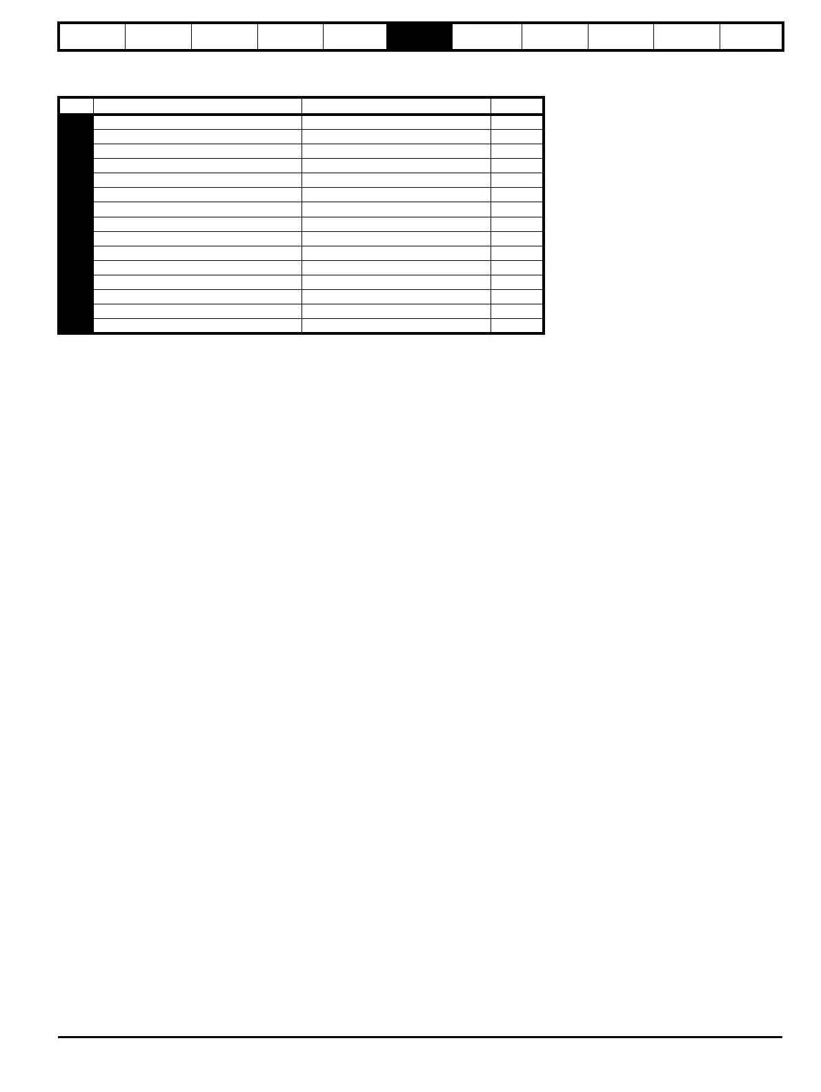
6.4 Diagnostic parameters
The following read only (RO) parameters can be used as an aid to fault diagnosis on the drive. See Figure 8-1 Diagnostics logic diagram on page 55.
No Function Range Type
81 Frequency reference selected ±Pr 02 Hz RO
82 Pre-ramp reference ±Pr 02 Hz RO
83 Post-ramp reference ±Pr 02 Hz RO
84 DC bus voltage 0 to Drive maximum VDC RO
85 Motor frequency ±Pr 02 Hz RO
86 Motor voltage 0 to Drive rating V RO
87 Motor speed ±9999 rpm RO
88 Motor current +Drive maximum A RO
89 Motor active current ±Drive maximum A RO
90 Digital I/O read word 0 to 95 RO
91 Reference enabled indicator OFF or On RO
92 Reverse selected indicator OFF or On RO
93 Jog selected indicator OFF or On RO
94 Analogue input 1 level 0 to 100 % RO
95 Analogue input 2 level 0 to 100 % RO