Safety
Information
Product
Information
Mechanical
Installation
Electrical
Installation
Keypad and
Display
Parameters
Quick Start
Commissioning
Diagnostics Options Parameter List
UL Listing
Information
30 Commander SK Size 2 to 6 Getting Started Guide
www.controltechniques.com Issue Number: 2
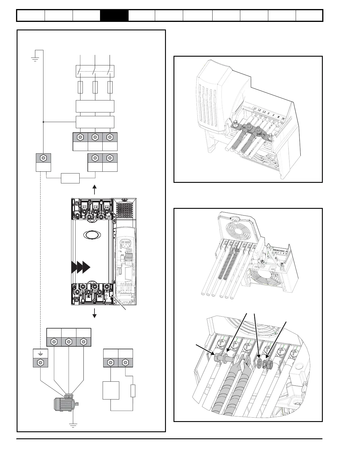
Figure 4-3 Size 4, 5 and 6 power connections
4.1.2 Ground connections
On Commander SK size 2, the supply and motor ground connections
are made using the grounding bridge that locates at the bottom of the
drive.
Figure 4-4 Size 2 ground connections
On Commander SK size 3, the supply and motor ground connections
are made using an M6 nut and bolt that locates in the fork protruding
from the heatsink between the AC supply and motor output terminals.
Figure 4-5 Size 3 ground connections
*See section 4.1.2 Ground connections ** See section 4.2.2 Heatsink
fan supply on page 31 for more information.
UVW
Motor
Optional ground
connection
+DC BR
Optional
braking
resistor
Thermal
overload
protection
device
Output connections
Input connections
Mains
Supply
L1 L2
Optional
line reactor
Optional
RFI filter
Fuses
L3
L1 L2 L3
+DC -DC
Internal
EMC filter
PE
Supply
ground
*
*
4 5 6
Size 6 only:
Heatsink
fan supply
connections
**
Plain washers
Spring washer
M6 bolt