CF3000 - USER MANUAL
101
Shop Monitor Unit - CSUM355
Installation
1. Separate the two halves of the unit.
2. Drill out (or knock out) the required cable entries in the surface mounting backbox.
3. Fit the back-box in position and pass the wires into it.
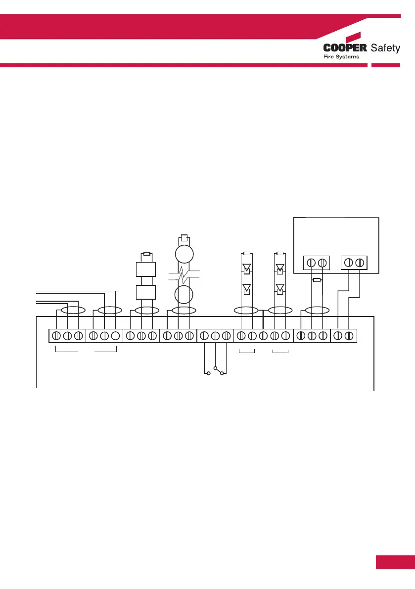
4. Connect the unit according to the diagram below.
Notes:
No addressing of the interface is required. See control panel operation for details.
Standard Connections
Notes:
1. This unit can only be used with FXN520 detector base and compatible detectors.
2. Only connect cable screen to its adjacent earth terminal.
3. The end of line resistor must always be fitted, even if the spur is unused.
4. Maximum spur length - See BS5839 Pt 1:2002 for zone coverage.
5. Maximum number of callpoints allowed is unlimited.
6. Detector zone end of line device is EOLM-1
7. Callpoint zone has end of line resistor
Section 5 - Appendix