CF3000 - USER MANUAL
103
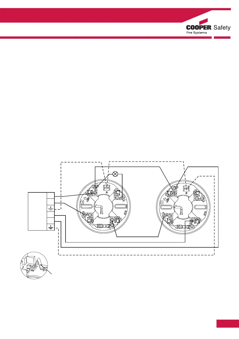
Detector Base Wiring - CAB300
Supply Voltage 18 - 30 V dc
Cable Size 0.5 - 2.5mm²
Recommended cable types FIRETUF, FP200 or MICC
Mounting hole centres 50 - 80mm
Wiring Hints
1. Each terminal is suitable for clamping up to 2 wires
2. Clamping of 2 wires of very different diameters under one screw is not recommended.
3. Suitable for mounting to mounting boxes with 50-80mm fixing centres. General If difficulty is
experienced when mounting the detector, this may be due to the following:
4. Wiring causing an obstruction - move or shorten wires.
5. Although the base is tolerant to uneven mounting surfaces, a very uneven surface may cause the base
to deform when the mounting screws are tightened down - loosen screws to reduce this or slide base
to a more flat position.
WARNING: Do not use high voltage testers when detectors or control panel are connected to the
system.
Section 5 - Appendix
Attention: If using the outer connection on terminal 2, ensure the operation of the switch
is not impeded and that there no shorts between terminal 2 and the switch contact.