2C9
2-3-12
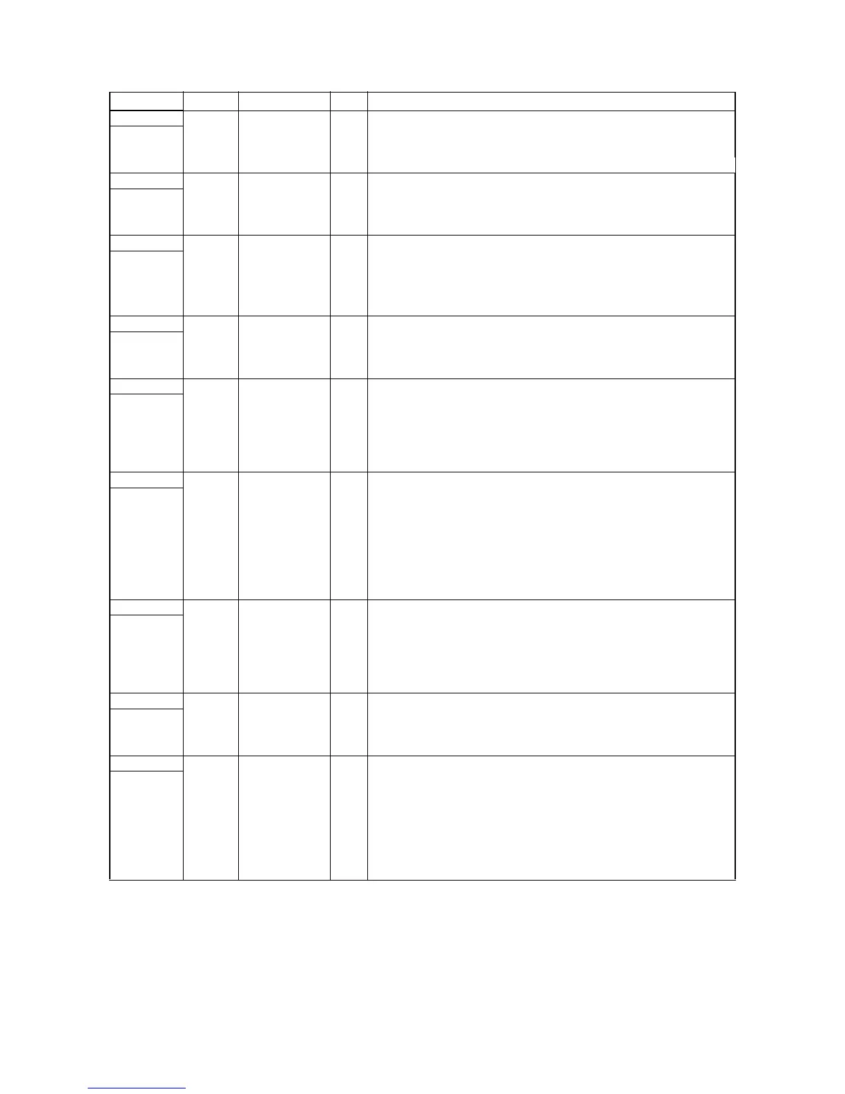
Connector Pin No. Signal I/O Description
YC13 1 +24 V1 O 24 V DC power supply for key counter
Connected
to the key
counter
2 KEYCN O Key counter count signal
3 S.GND - Ground
4 KEYENBN I Key counter set signal
YC14 1 COMDA O EM control signal (A)
Connected
to the exit
motor
2 COMDNB O EM control signal (_B)
3 COMDNA O EM control signal (_A)
4 COMDB O EM control signal (B)
YC15 1 P.GND - Ground
Connect to
the exit
switch and
feedshift
2 EXTSMN I ESW on/off
3 SEPSWN I FSSW on/off
4 +5 V2 O 5 V DC power supply for ESW/FSSW
YC16 1 ISMDA O SM control signal (A)
Connected
to the scan-
ner motor
2 ISMDNB O SM control signal (_B)
3 ISMDNA O SM control signal (_A)
4 ISMDB O SM control signal (B)
YC17 1 LAMPN O EL on/off
Connected
to the
inverter PCB
2 P.GND - Ground
3 +24 V1 O 24 V DC power supply for inverter PCB
4 +24 V1 O 24 V DC power supply for inverter PCB
5 P.GND - Ground
6 LAMPN O EL on/off
YC18 1 +5 V2 O 5 V DC power supply for SHPSW
Connected
to the origi-
nal detec-
tion switch
and scan-
ner home
position
switch
2 HPSWN I SHPSW on/off
3 S.GND - Ground
4 +5 V2 O 5 V DC power supply for ODSW
5 OPSWN I ODSW on/off
6 S.GND - Ground
YC19 1 +5 V2 O 5 V DC power supply for OSDS
Connected
to the origi-
nal size
detection
sensor
2 ORGLSWN I OSDS on/off
3 S.GND - Ground
YC20 1 +5 V I 5 V DC power supply from PSPCB
Connected
to the power
source PCB
2 S.GND - Ground
3 P.GND - Ground
4 +24 V2 I 24 V DC power supply from PSPCB
YC21 1 +24 V I 24 V DC power supply from PSPCB
Connected
to the power
source PCB
2 +24 V1 I 24 V DC power supply from PSPCB
3 +24 V1 I 24 V DC power supply from PSPCB
4 P.GND - Ground
5 P.GND - Ground
6 COUNTN - Not used
7 MHEATN O FH-M on/off
8SHEATN OFH-S on/off


 To Next Page