2C9-6.0
1-3-13
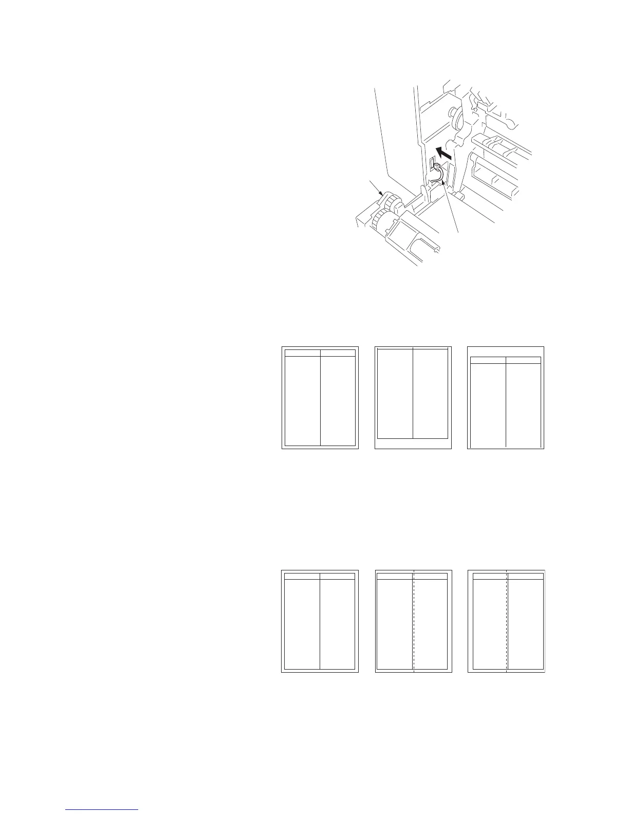
11. Open the conveyer unit and connect the
connector of the duplex unit to the copier.
12. Reattach the removed parts to their original
positions.
13. Connect the copier power plug to the wall
outlet and turn the copier power switch on.
Figure 1-3-24
Adjusting the leading edge timing
1. Run maintenance mode 034.
Press the image quality mode key until
"Text" is lit. (group 1)
Press the exposure key until "exp1" is flash-
ing. (mode 6)
Make a test copy in the duplex mode to
check the image. If an adequate image can-
not be obtained, carry out the following
adjustment.
2. If a copy example a is obtained, increase
the adjustment value.
If a copy example b is obtained, decrease
the adjustment value.
Setting range: -5.0 - 10.0
3. Make a test copy again.
4. Repeat steps 2 and 3 until an adequate
image is obtained.
Figure 1-3-25
Adjusting the center line
1. Run maintenance mode 034.
Press the image quality mode key until
"Text" and "Photo" are lit. (group 2)
Press the exposure key until "exp1" is flash-
ing. (mode 6)
Make a test copy in the duplex mode to
check the image. If an adequate image can-
not be obtained, carry out the following
adjustment.
2. If a copy example a is obtained, increase
the adjustment value.
If a copy example b is obtained, decrease
the adjustment value.
Setting range: -8.0 - 10.0
3. Make a test copy again.
4. Repeat steps 2 and 3 until an adequate
image is obtained.
Figure 1-3-26
Connector
Duplex unit
Adequate image Copy example a Copy example b
Adequate image Copy example a Copy example b