Cosman G4 Radiofrequency Generator Service Manual (SPI 11291 Rev A)
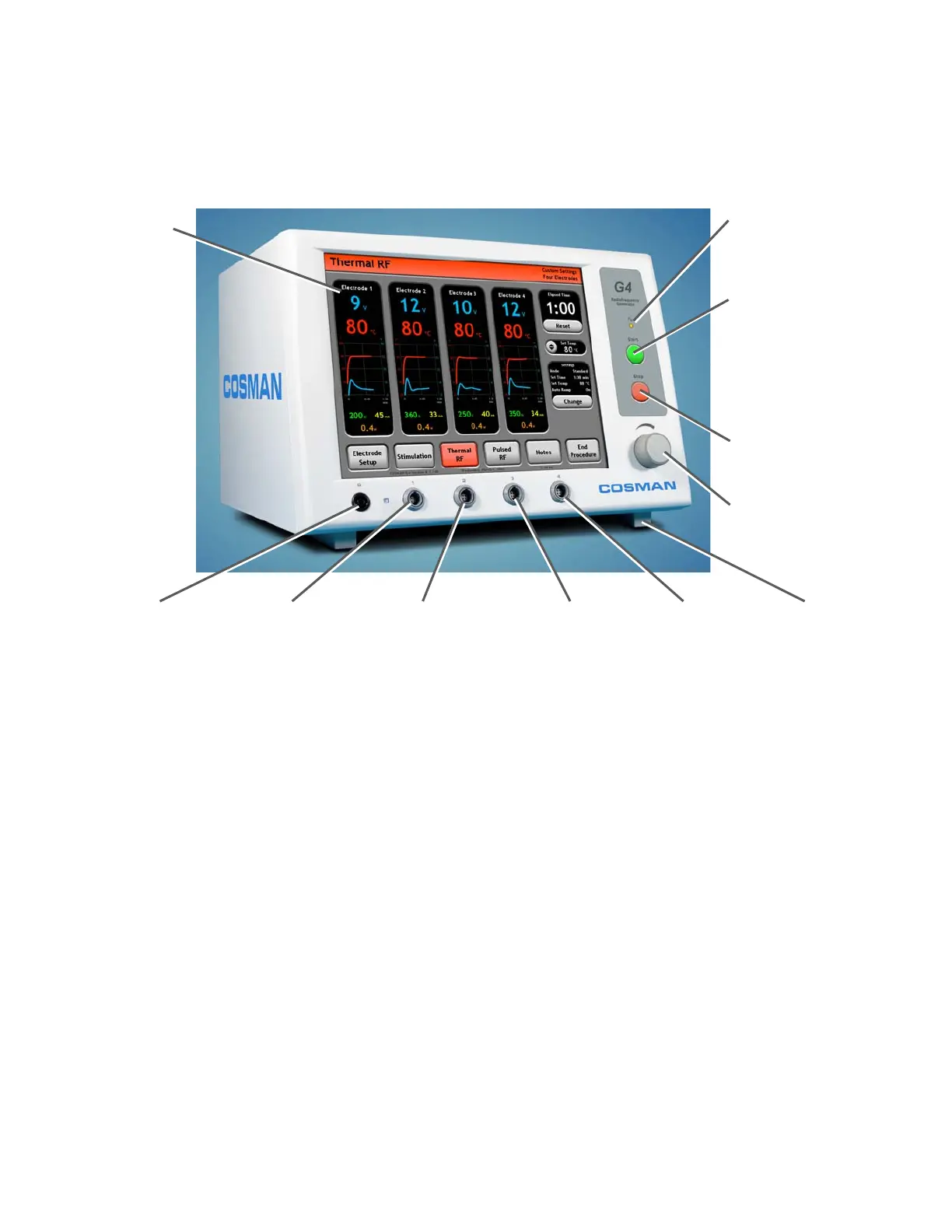
2. Chassis Layout
2.1 Front Panel Layout
Front-panel Start Button:
Turn on electrode output
when the Stimulation (Sec.
8.1 & 9.1), Thermal RF
(Sec. 8.2 & 9.2), or Pulsed
RF (Sec. 8.3 & 0) screens
are displayed.
Touch Screen
Output On Indicato
:
Illuminated when any
electrode out
ut is on
Output Control Knob:
Manual output ramping.
Disabled in some modes.
Front-panel Stop Button:
Turn off electrode output
Reference Ground
Pad Connection (G)
Adjustable
Feet
Electrode Output
Connection 1
Electrode Output
Connection 2
Electrode Output
Connection 3
Electrode Output
Connection 4
Notes:
• Electrode connections are made by attaching a CB112-TC cable to an “Electrode Output
Connection” jack (gray) shown above.
• Patient “Reference” connection is made by attaching a CB103-B black cable or the DGP-PM Ground
Pad to the “Reference Ground Pad Connection” jack (black) shown above.
Section 2