Do you have a question about the Cosman G4 and is the answer not in the manual?
Classifications per EN 60601-1.
Compliance with electrical safety and EMC standards.
Critical safety warnings for operating the device.
Detailed electrical safety information and precautions.
Warnings and precautions for safe operation and patient care.
Explains device symbols, controls, and connections.
Identifies mains power on/off switches.
Describes start, stop buttons, and output control knob.
Details electrode and reference ground pad connection ports.
Identifies connections, readings, and status indicators.
Lists device certifications, compliance, and identification symbols.
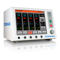
Identifies and describes components on the front panel.
Identifies and describes components on the back panel.
Overview of the G4 lesion generator capabilities.
Specifies the intended uses of the G4 generator.
Lists G4 system components and unpacking notices.
Describes the sequence of screens from startup to main menu.
Configuration of system date, time, language, and audio settings.
Procedure for calibrating the touch screen interface.
Procedures for testing the G4 unit functionality.
Explains error messages and common error conditions.
Details starting a procedure and managing presets.
Setting up electrodes, assigning labels, and understanding the interface.
Determines RF type, active electrodes, and labels.
Details distinguishing characteristics and functions of the Graphing interface.
Explains Stimulation screen, controls, and readings.
Configures control units, auto ramp, and pulse parameters.
Details Thermal RF screen, including timer, set temp, and output controls.
Configures mode, stagger start, auto ramp, set temp, and set time.
Details Pulsed RF screen, including timer, E-dose, and output controls.
Configures stagger start, auto ramp, E-dose, and pulse parameters.
Details distinguishing features of the One Touch interface.
Explains One Touch stimulation controls, modes, and readings.
Configures control units, auto ramp, and pulse parameters in One Touch.
Explains One Touch Thermal RF controls, modes, and readings.
Configures mode, stagger start, auto ramp, and temperature settings.
Explains One Touch Pulsed RF controls, E-dose, and output.
Configures stagger start, auto ramp, E-dose, and pulse parameters.
Recommended methods for sterilizing specific components.
Guidelines for cleaning the generator and accessories.
Information on servicing, testing, and fuse replacement.
Identifies issues and their potential causes for troubleshooting.
Details voltage, power, environmental operating and storage conditions.
Specifies impedance, stimulator, and RF output characteristics.
Graph showing output power relative to knob setting across resistances.
Graph showing output power relative to resistance for half and full output.
Lists part numbers and descriptions for available accessories.
Lists all test equipment necessary for system maintenance.
Verifies that the application program files are loaded correctly.
Tests the oscillator resonance using specific loads and oscilloscope.
Verifies the functionality and display of the touch screen.
Calibrates temperature display accuracy using water baths.
Calibrates high voltage measurement accuracy using oscilloscope.
Calibrates peak voltage display accuracy using oscilloscope.
Verifies the lockout functionality when output is turned off.
Verifies accuracy of voltage, current, and wattage displays.
Tests the functionality of the lesion timer.
Verifies the automatic temperature control feature.
Checks temperature variation with different cables and output levels.
Verifies impedance stability across output levels with cables.
Tests impedance readings at different output levels and configurations.
Verifies the system behavior when temperature measurement is off.
Calibrates the audio volume and frequency response.
Verifies stimulator output parameters like voltage, current, rate, and duration.
Tests the maximum RF output voltage.
Performs high potential (HIPOT) tests for insulation integrity.
Measures AC mains and patient leakage currents.
Tests the integrity of the protective earth ground connection.
Final visual inspection, functional checks, and voltage configuration.
Illustrates the main components and their interconnections.
Detailed schematic diagram of the backplane board.
Detailed schematic diagram of the RMS Stim board.
Detailed schematic diagram of the Current board.
Detailed schematic diagram of the USB Card board.
Detailed schematic diagram of the Power Supply board.
Shows component placement on the topside of the backplane board.
Shows component placement on the topside of the RMS Stim board.
Shows component placement on the Current board.
Shows component placement on the USB Card board.
Shows component placement on the topside of the Power Supply board.
Lists all components for the backplane board assembly.
Lists all components for the RMS Stim board assembly.
Lists all components for the Current board assembly.
Lists all components for the USB Card board assembly.
Lists all components for the Power Supply board assembly.
Records results for initial display, touch screen, RF output, and lesion timer tests.
Records results for Hipot, leakage, and ground bond tests.
| Engine Type | 4-Stroke OHV |
|---|---|
| Engine Displacement | 212cc |
| Fuel Tank Capacity | 4 Gallons |
| Noise Level | 68 dB |
| Starting Method | Recoil Start |