Cosman G4 Radiofrequency Generator Service Manual (SPI 11291 Rev A)
9. One Touch Interface
The One Touch interface is one of two user interfaces available for operation of the generator in
Stimulation, Thermal RF, and Pulsed RF modes. The other is Graphing interface (Section 8). Choice of
user interface is primarily a matter of user preference, since almost all generator functions are available in
both interfaces. The One Touch interface has the following distinguishing characteristics.
• On-screen Start/Stop button: An on-screen Start/Stop toggle button is available to enable and
disable electrode output. The mechanical Start and Stop buttons to the right of the Touch Screen
are still fully functional, but do not need to be used.
• Stimulation Incremental Controls: When the Stimulation “Auto Ramp” setting is Off (see Sections
9.1 & 9.1.2), Stimulation output is incremented and decremented using on-screen buttons, NOT that
Output Control Knob.
• Thermal and Pulsed RF Automatic Control: Automatic output ramping (“Auto Ramp”) cannot be
disabled for Thermal RF and Pulsed RF output unless Automatic Temperature Control is disabled
(see Sections 9.2.2 and 9.2.4). Manual output ramping using the Output Control knob can be
enabled by setting “Auto Ramp” to Off in the Graphing interface (see Section 8).
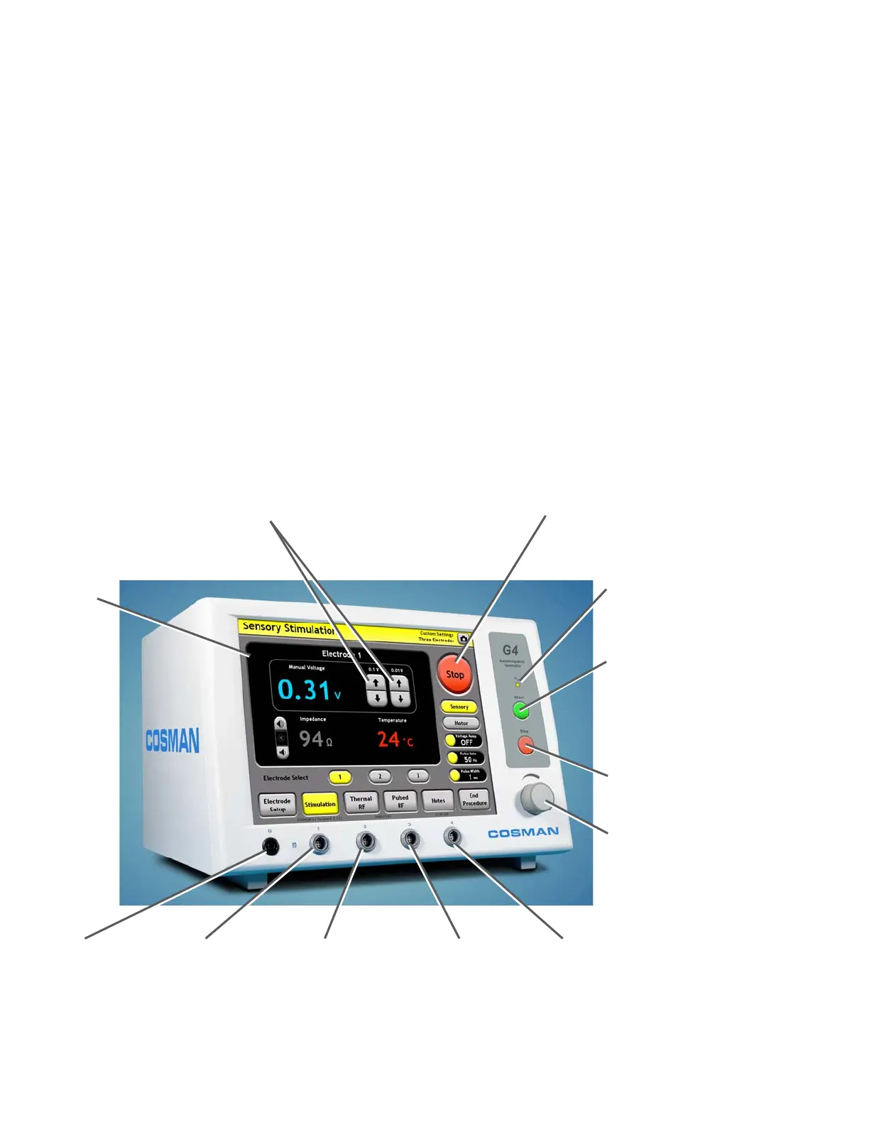
Touch Screen
Stimulation Increment/Decrement Buttons:
vailable on the One Touch Stimulation
screen when Stimulation Auto Ramp = Off.
Output Control Knob:
Manual output ramping in
TRF & PRF mode if
Set/Max Temp=Off.
Disabled at all other times.
On-screen Start/Stop Button:
• Press “Start” to turn electrode
output on.
• Press “Stop” to turn electrode
output off.
Output On Indicato
:
Illuminated when any
electrode out
ut is on
Front-panel Start Button:
Turn on electrode output
when the Stimulation (Sec.
9.1), Thermal RF (Sec.
9.2), or Pulsed RF (Sec. 0)
screens are displayed.
Front-panel Stop Button:
Turn off electrode output
Reference Ground
Pad Connection (G)
Electrode Output
Connection 1
Electrode Output
Connection 2
Electrode Output
Connection 3
Electrode Output
Connection 4
Section 9