Cosman G4 Radiofrequency Generator Service Manual (SPI 11291 Rev A)
8. Graphing Interface
The Graphing interface is one of two user interfaces available for operation of the generator in Stimulation,
Thermal RF, and Pulsed RF modes. The other is One Touch interface (Section 9). Choice of user interface
is primarily a matter of user preference, since almost all generator functions (including full automatic ramp
and temperature control) are available in both interfaces. The Graphing interface has the following
distinguishing characteristics.
• Graphing: In Stimulation mode, the output level is plotted as a bar graph (see Section 8.1). In
Thermal and Pulsed RF modes, Voltage and Temperature are plotted a function of time when RF
output is enabled (see Sections 8.2 and 8.3).
• Stimulation Level Annotation: The user can manually mark Stimulation levels (see "Mark Level"
button in Section 8.1) for review in the Procedure Record.
• RF Timer Reset: The Thermal and Pulsed RF timer can be manually reset when output is on (see
Timer, Sections 8.2 & 8.3).
• Manual Thermal RF Temperature Increment: The target Temperature (see "Set Temp Panel",
Section 8.2) for Thermal RF mode can be increased manually in 5°C steps when electrode output is
on.
• Manual Output Control: When the “Auto Ramp” setting is Off (see Sections 8.1.2, 8.2.2 & 8.3.2),
the Stimulation, Thermal RF, and Pulsed RF output levels can be controlled with the Output Control
Knob. Auto Ramp can be disabled in the One Touch interface (Section 9) only if Automatic
Temperature Control is disabled (for use with non-temperature-monitoring electrodes).
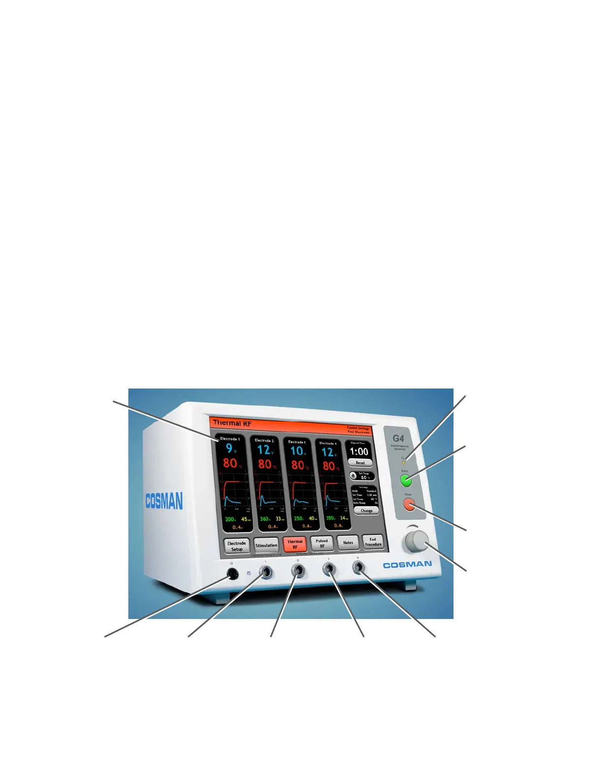
Output On Indicato
:
Illuminated when any
electrode out
ut is on
Touch Screen
Front-panel Start Button:
Turn on electrode output
when the Stimulation (Sec.
8.1), Thermal RF (Sec.
8.2), or Pulsed RF (Sec.
8.3) screens are
displayed.
Front-panel Stop Button:
Turn off electrode output
Output Control Knob:
Manual output ramping
when Auto Ramp = Off.
Disabled if Auto Ramp =
On
Reference Ground
Pad Connection (G)
Electrode Output
Connection 1
Electrode Output
Connection 2
Electrode Output
Connection 3
Electrode Output
Connection 4
Section 8