Cosman G4 Radiofrequency Generator Service Manual (SPI 11291 Rev A)
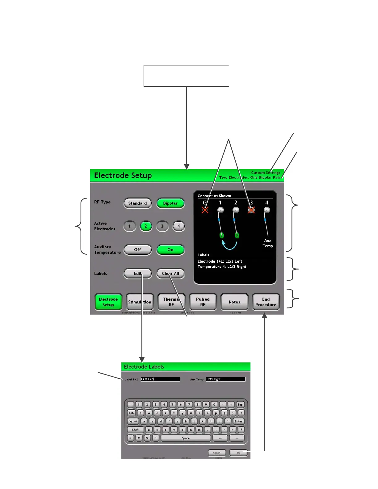
7. Electrode Setup Screen
Label Text: A labels can be
assigned to each electrode,
or bipolar electrode pair.
Settings Buttons:
Buttons highlighted
in green determine
the Electrode Setup
that applies to the
Stimulation,
Thermal RF, and
Pulsed RF screen.
These settings are
described in Section
7.1.
Settings Graphic:
Shows the current
Electrode Setup settings.
ttach electrodes, and
ground pad to the
Electrode output
connections on the front
panel (Section 2.1) as
shown on the screen.
Edit Button: Launches a
keyboard to edit labels for the
active electrode
Press “Ok”: Accept
entered text
Press “Cancel”:
Discard entered text
Clear All Button:
Erases all electrode
labels
Labels: Lists the current
electrode labels.
Mode Ba
: Access
other procedure
screens:
• Electrode Setup
(Section 7)
• Stimulation
(Sec. 8.1 & 9.1)
• Thermal RF
(Sec. 8.2 & 9.2
• Pulsed RF
(Sec. 8.3 & 0)
• Notes
• End Procedure
Disconnect electrodes and
probe from any output
connector shown on the screen
marked with a red “X”.
Start Procedure
Section 6
Current Electrode Setup
Current Personal
Settings Preset
Electrode Labels
Keyboard screen
Section 7