12 GLOSSARY INSTALLATION MANUAL
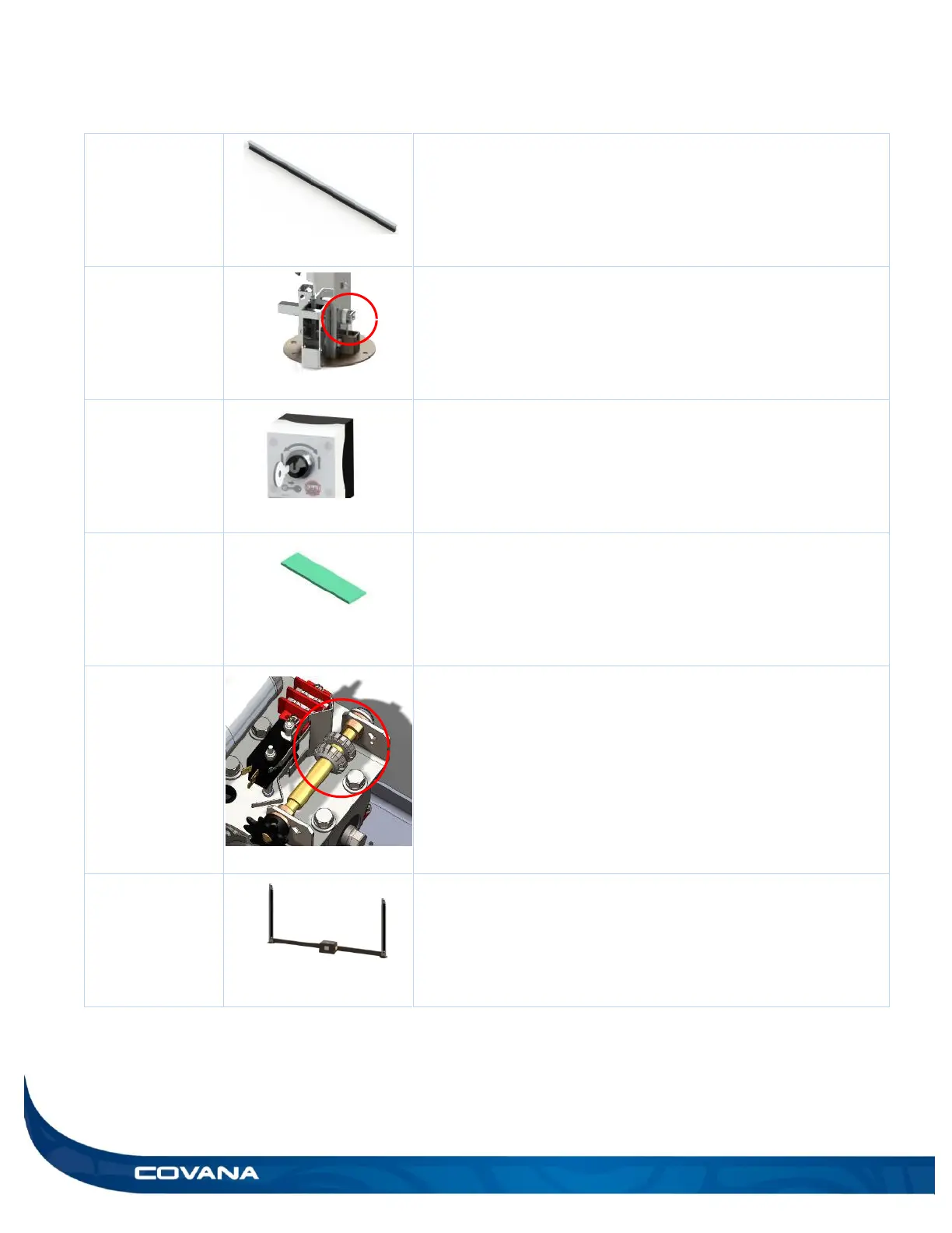
The I-beams are the aluminum extrusions installed between the
panels.
The jack lock brackets prevent the non-motor-side jacks from
extending during shipping and installation. Do not remove this
bracket until the drive shaft is connecting the motor-side jack to the
non-motor-side jack. Follow the installation steps carefully.
WARNING: There is a risk of injury if this step is not done properly.
The key switch is used to operate the Covana cover.
The installation foam is used during the installation process to
protect the hot tub from direct contact with the cover. Use the
provided masking tape to temporarily stick the pieces of foam on
the surface of the hot tub.
The limit switches are located in the operator. They control the
minimum and maximum travel height of the Covana cover. Refer to
the Limit Switch Adjustment section for further details.
The motor frame is composed of the two motor-side jacks and the
operator.