INSTALLATION MANUAL INSTALLATION 19
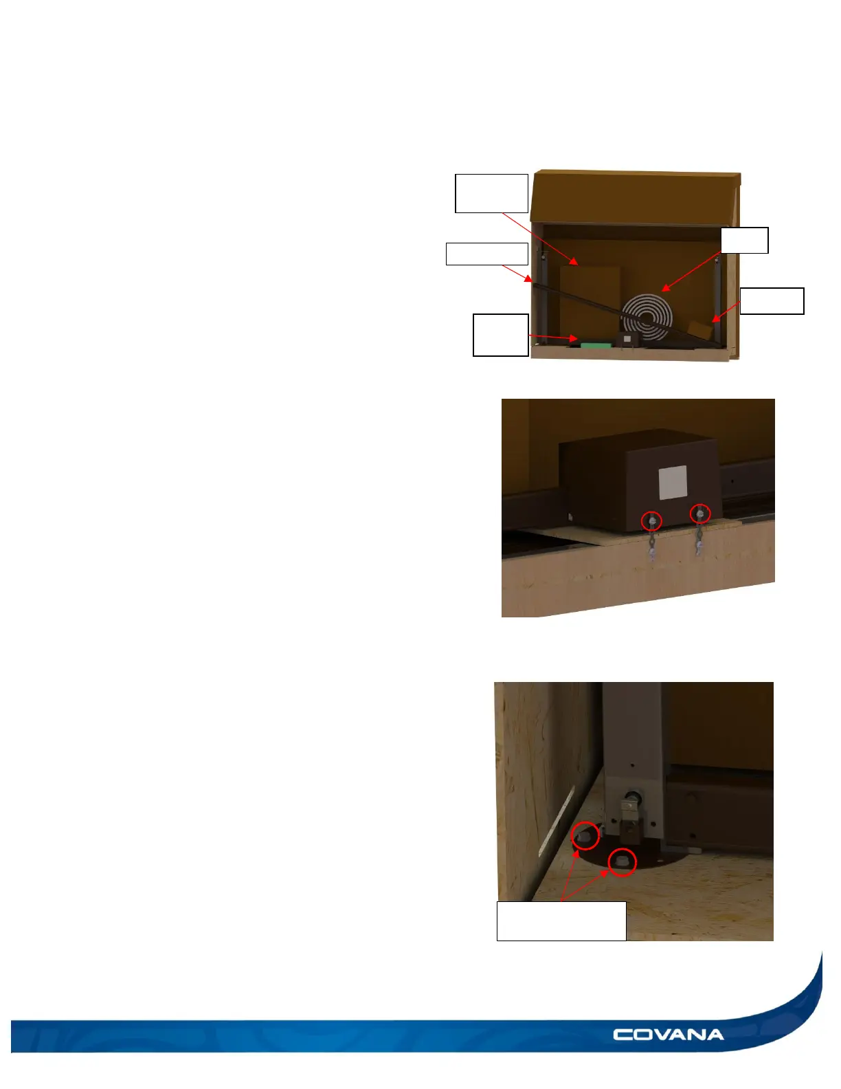
5) Remove the C-channels, the escape hatch box,
the part box, the foam pieces and the seal from
the crate. Temporarily put these items in a safe
place. (Figure 29)
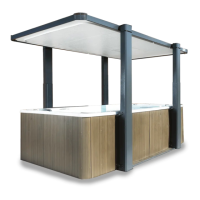
6) Use a slotted screwdriver to remove the two
slotted #10-24 x 3/8″ screws holding the operator
in place. (Figure 30)
7) Bend the metal strapping all the way back and
reinstall the screws on the operator. (Figure 30)
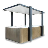
8) Use the 3/8″ (10 mm) socket wrench to unscrew
the hexagonal 1/4″-14 x 2″ lag bolts on the bottom
of both jacks. There are two lag bolts per jack.
(Figure 31)