27
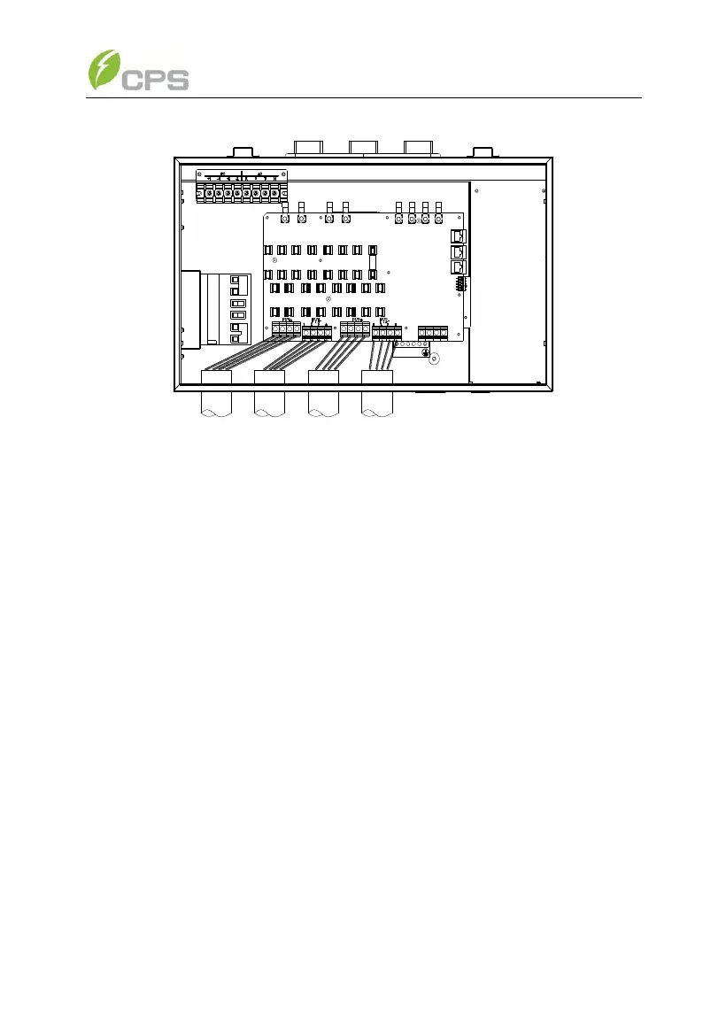
Figure 3-12 Wire connection of DC input
(e) The standard configuration is “Parallel mode” with 1MPPT working
alone. If it needs to switch to the “Independent mode” with 2MPPTs working
independently, please remove the red wire and black wire in the wiring box.
(As shown in Figure 3.13)
For the inverter with 2 MPPT working independently, disconnect J1 (IN1+)
with J3 (IN2+) wire socket (in the Wiring box) through the red; disconnect J2
(IN1-) with J4 (IN2-) wire socket through the black wire in the wiring box, as
shown in Figure 3-13: