29
Figure 3-14 Diagram for wire stripping of AC output
(c) Crimp the terminal as shown in Figure 3-15:
Figure 3-15 Diagram for terminal crimping of AC output
(d) Connect the L1, L2, L3 and Neutral (red, black, blue, grey) AC output
wires to the corresponding terminals on the PCB board.
(3) Wire connection for grounding:
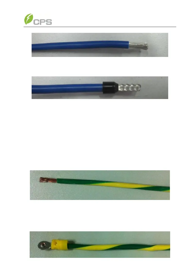
(a) The Gnd wire (Equipment grounding conductor) is recommended to
be green or green with continuous yellow stripes, per National
Electrical Code. Insert the cable through the steel conduit and strip
the skin 0.4 inch off the cables as shown in Figure 3-16:
Figure 3-16 Diagram for wire stripping of grounding conductor
(b) Crimp the terminal with the ring terminal in the accessory kit as
shown in Figure 3-17: