30
Figure 3-17 Diagram for terminal crimping of grounding conductor
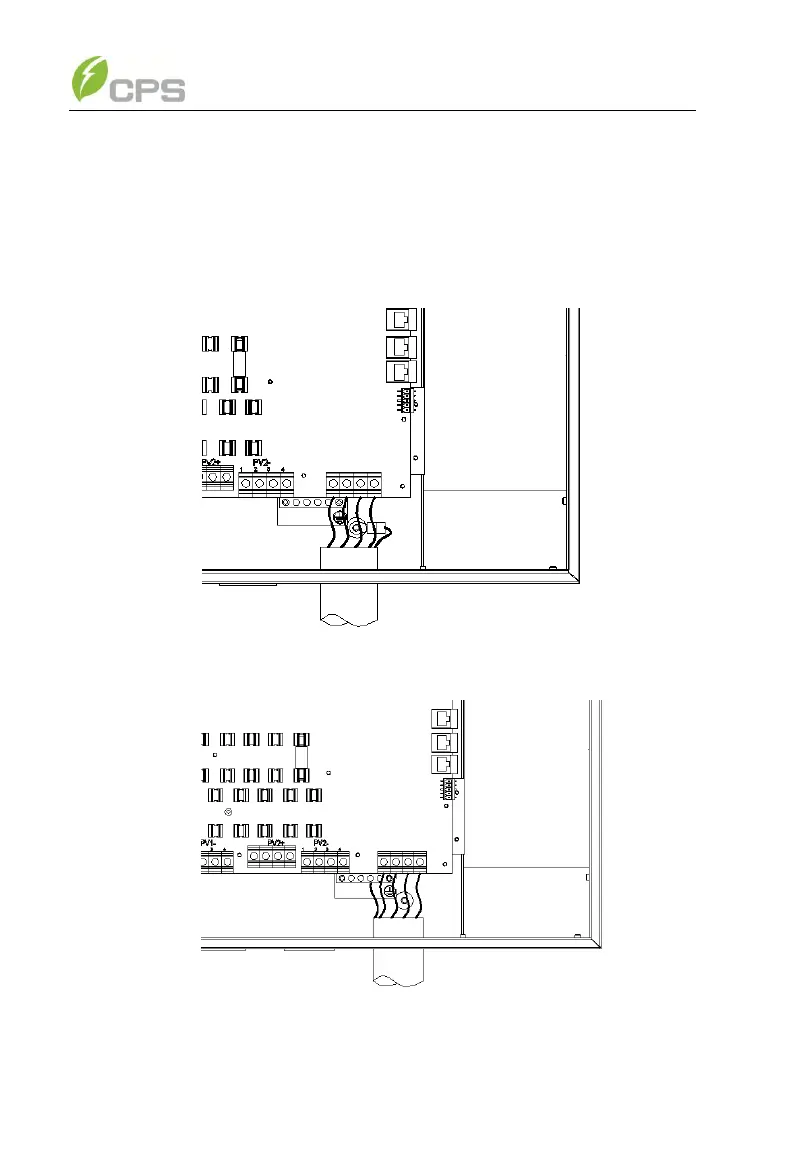
(c) Connect the Gnd cable with a M5 nut at the marked place on the
lower right side of the Wiring box, as shown in Figure 3-18(a). The
Gnd cable can also be connected to the copper stick as shown in
Figure 3-18(b).
Figure 3-18(a) Diagram of AC output and ground cable connection
Figure 3-18(b) Diagram of AC output and ground cable connection