32
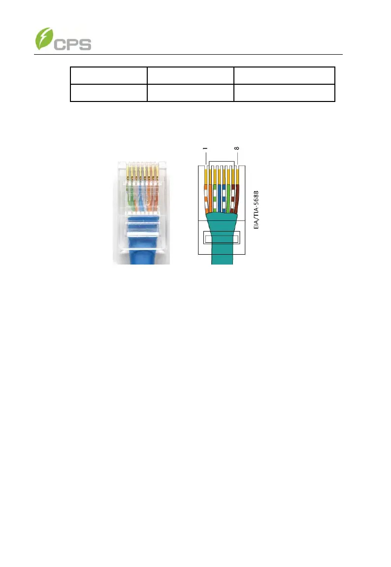
(2) The wires are labeled 1~8 from left to right, as shown in Figure 3-19:
Figure 3-19 Diagram of RS485-1/2 wiring
(3) RS485 network connection:
When the inverters are monitored via the RS485 communication, the unique
RS485 address for each inverter can be set through the LCD interface. Up to 31
inverters can be connected together in the RS485 communication network. The
Daisy-chain topology is recommended for the RS485 network connection, as shown
in Figure 3-20. Other communication topologies, such as the star networks, are not
recommended.