33
Figure 3-20 RS485 connection between inverters and datalogger
(4) A terminal resistance of 120 ohms connected between Pin 1 and Pin 3 of
RS485-1/2 of the first inverter in the multiple inverters string and data logger as
shown in Figure 3-20 is recommended.
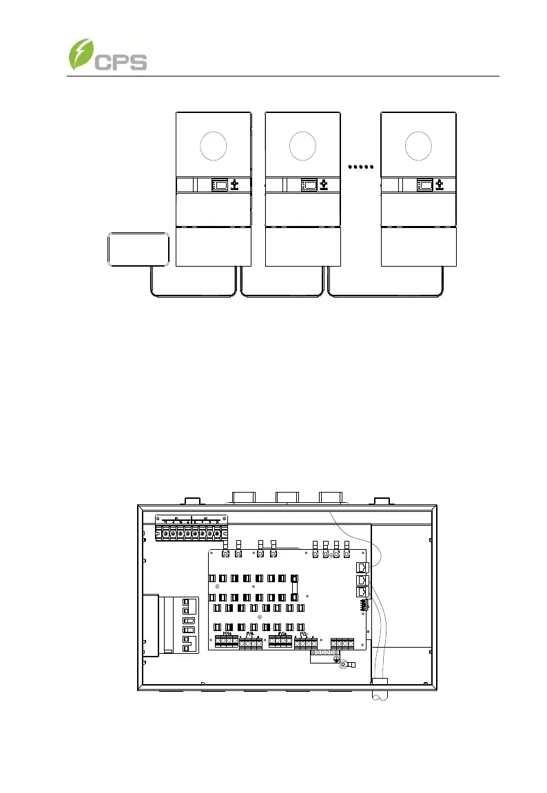
(5) The connection inside the Wiring box of the inverter after the first one
is shown in Figure 3-21:
Figure 3-21 Diagram of communication wiring