24
B. Aligning the mark on the wire-box with the bracket (Figure 3-15),
hang the wire-box on the right side of the wall bracket. Push the
wire-box left to its final position meeting the main inverter
enclosure.
Figure 3-15 Wire-box Position
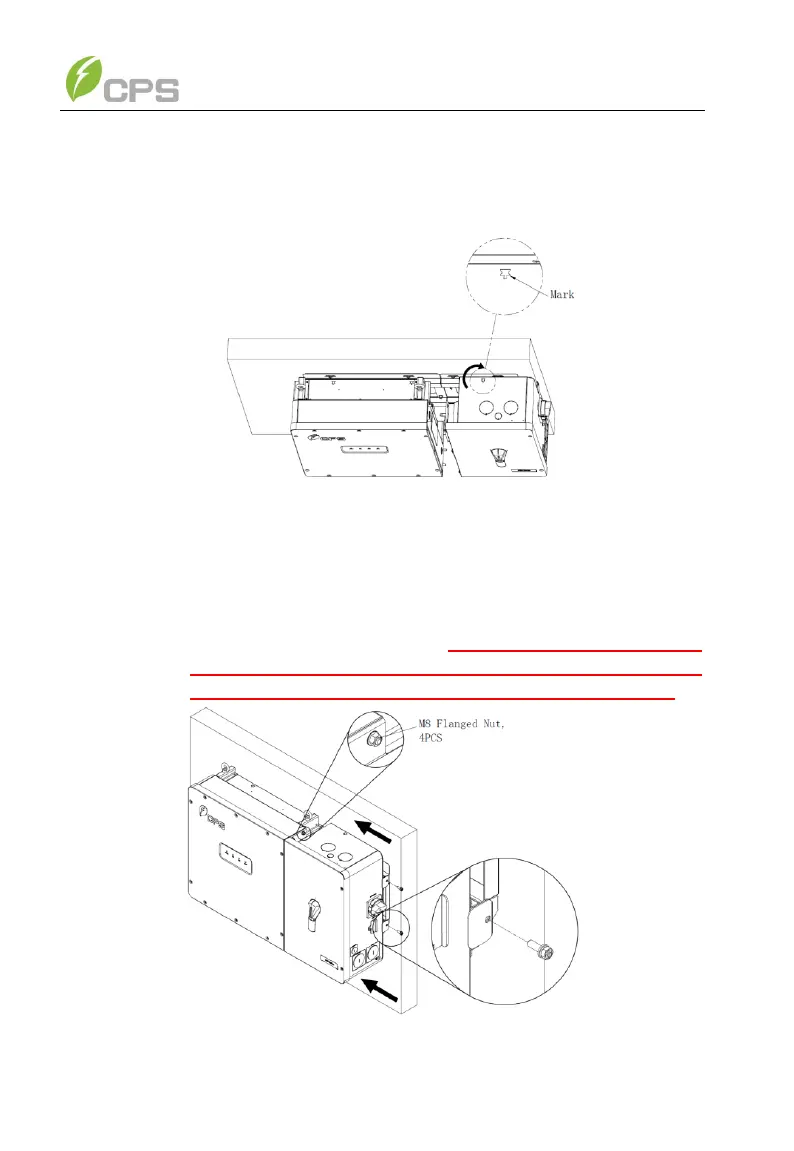
C. Connect the wire-box to the main enclosure, using the M8
Flanged Nut (4pcs) (torque: 12.5Nm (110.6 in-lbs). Secure the
wire-box to the bracket with M6x18 combination screw (torque:
6Nm (53 in-lbs)) (Figure 3-16). This connection provides the
ground bond for the Inverter (Main) Enclosure. Failure to
properly install may result in shock or equipment failure.
Figure 3-16 Installation of the Wire-box