Unpacking and Setting Up the CompuCarve System
1. Remove the top packaging foam: After opening the shipping box,
carefully remove the top molded foam packing from the machine.
Located in the top tray are items B through K listed above.
2. Remove the machine from box: With a helper, lift out the machine
and place it on a sturdy table or bench. Fold down the Outfeed Support
Tables. Remove the plastic film covering the top clear safety cover.
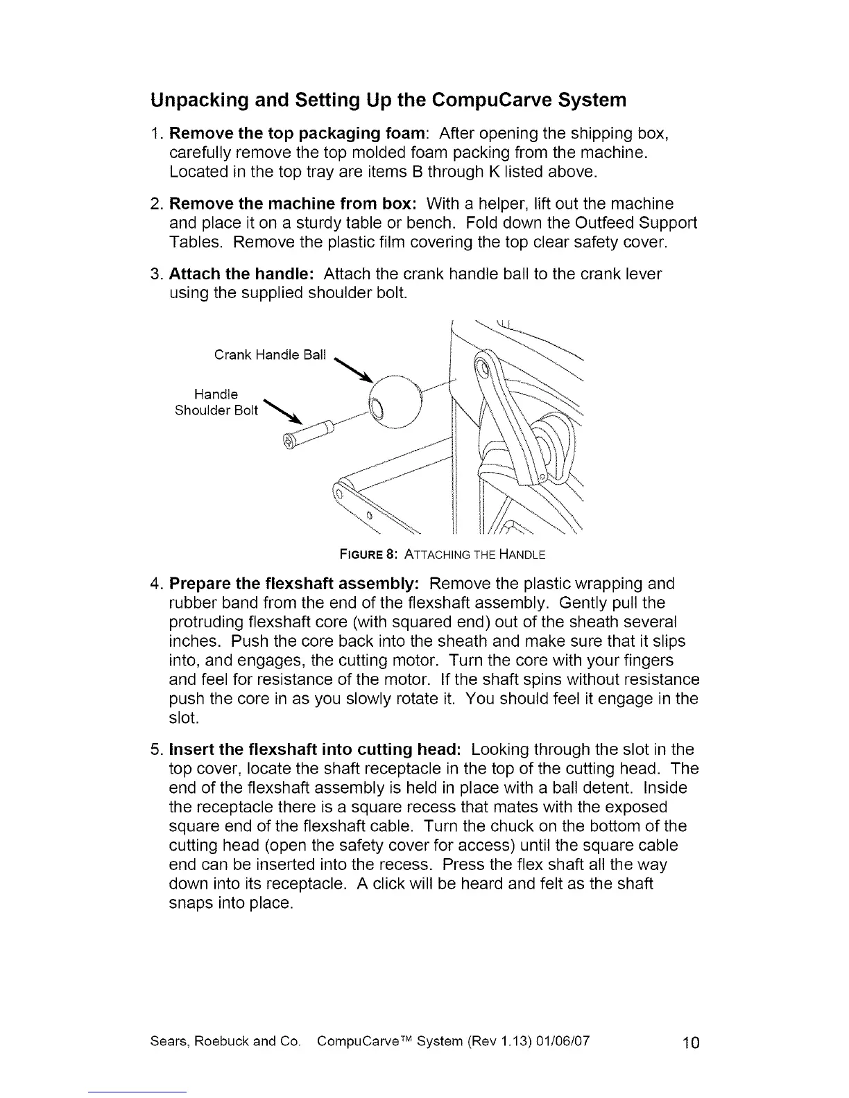
3. Attach the handle: Attach the crank handle ball to the crank lever
using the supplied shoulder bolt.
Crank Handle Ball
Handle
Shoulder Bolt
FIGURE 8: ATTACHING THE HANDLE
4. Prepare the flexshaft assembly: Remove the plastic wrapping and
rubber band from the end of the flexshaft assembly. Gently pull the
protruding flexshaft core (with squared end) out of the sheath several
inches. Push the core back into the sheath and make sure that it slips
into, and engages, the cutting motor. Turn the core with your fingers
and feel for resistance of the motor. If the shaft spins without resistance
push the core in as you slowly rotate it. You should feel it engage in the
slot.
5. Insert the flexshaft into cutting head: Looking through the slot in the
top cover, locate the shaft receptacle in the top of the cutting head. The
end of the flexshaft assembly is held in place with a ball detent. Inside
the receptacle there is a square recess that mates with the exposed
square end of the flexshaft cable. Turn the chuck on the bottom of the
cutting head (open the safety cover for access) until the square cable
end can be inserted into the recess. Press the flex shaft all the way
down into its receptacle. A click will be heard and felt as the shaft
snaps into place.
Sears, Roebuck and Co. CompuCarve TM System (Rev 1.13) 01/06/07 10
 Loading...