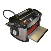
Measuring a Board
The Measure Board function allows the user to measure the width or
length of an existing board. Simply load a board in the typical way and
press Key #7 on the keypad or use the arrows from the main menu. The
display will then ask for the direction the user wishes to measure.
Carving a Project
A project is a set of related design elements (patterns or figures) created
with the CarveWright design software and stored on the memory card.
These stored projects are accessed from the keypad. Simply press the
Projects (Key #1) shortcut key to open the Projects Menu which can then
be browsed using the up and down arrows. The desired project can be
selected by pressing ENTER. Upon selection of a project from the project
menu, the CompuCarve will lead the user through the preparation
process. The first instruction will be to insert a board.
Inserting a Board
Proper installation of the workpiece is critical to the performance and
continued operation of the machine. To properly insert a workpiece:
1. Press down on the sliding guide plate release lever and move the
sliding guide plate to the right so that it will clear the width of the
workpiece.
,
Check the bottom of the workpiece for features that will make it
unusable in the machine. The bottom surface of the workpiece
where it contacts the squaring plate must be flat and level for a
width of at least 3/8 inches along the bottom edge to allow the
Board Tracking Sensor to accurately calculate the position of the
workpiece at all times (see Figure 17). If a workpiece does not
have the required surface available for the sensor to follow (e.g., if
it is already carved on the back), it will be necessary to fasten the
workpiece to a sled or carrier jig to do further work on it. If a
workpiece is slightly cupped or bowed, the workpiece should be
inserted with the cup or bow facing down.
It is also important to note that any existing features on the
workpiece (such as previous carving, knots, holes, paint, rounded
edges etc) may cause the machine sensors to incorrectly measure
the workpiece. To minimize this risk make sure that there are no
features directly underneath the cutting head and in line with the
side-to-side motion when the workpiece is loaded. These features
can also be masked from the sensors with standard masking tape.
3. Lay the workpiece on the traction drive so that it is centered
lengthwise under the head.
4. Push the board firmly up against the squaring plate.
Sears, Roebuck and Co. CompuCarve TM System (Rev 1.13) 01/06/07 20

 Loading...