36
Released on 10/31/05 - X800058A UV Pure Technologies Inc. © 2005
No part of this document may be photocopied, reproduced, transmitted, or translated to another language without the
prior written consent of UV Pure Technologies Inc.
For additional info call 1-888-407-9997 or email info@uvpure.com
or visit www.uvpure.com
shaft must fit through the U-cup seal (9) (the lips of the seal must always face the
water side) and protrude outside the bottom end cap (5). The wiper assembly is
fully inserted when the groove on the shaft is visible outside the bottom end cap.
Replace the wiper retaining ring (18) by inserting it into the grooved area on the
wiper assembly shaft. Replace the rubber washer (20).
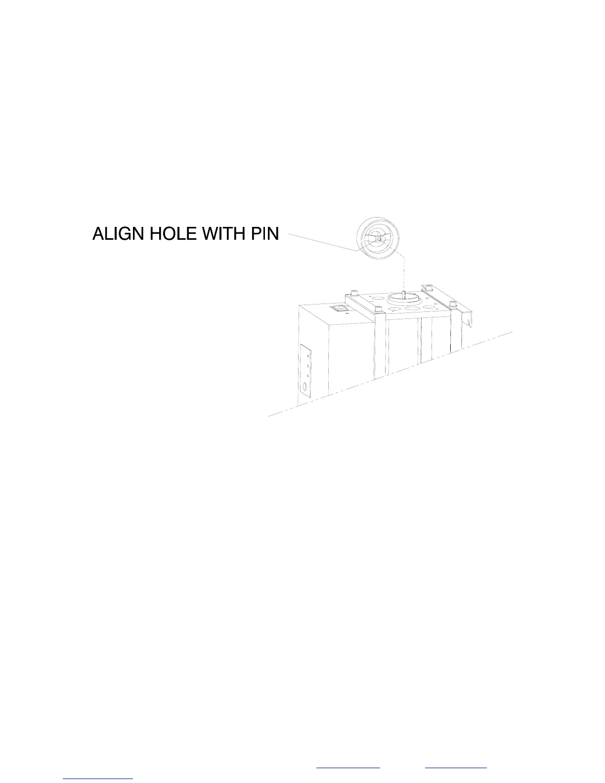
Step 2: Ensure the quartz O-ring seal (6) is in place around the quartz sleeve
and then replace the top end cap (2) by aligning the small hole in the thin plate
with the top pin of the wiper assembly (12). This will help center both parts.
Figure 4D
Step 3: Replace the top bracket (1) over the top end cap (2). The collar of the
end cap will fit snugly in the hole in the bracket and align itself. Tighten the
fasteners (16) in an alternating pattern (
lock washers (15) must be installed).
Step 4: Reconnect the wiper motor (17) to the bottom bracket (4). The flat blade
on the wiper motor shaft must be aligned with the slot in the round wiper shaft –
the wiper shaft can be rotated counter-clockwise to accommodate this. Remove
the foam pad in order to see the motor shaft. Once this alignment is done, the
motor plate and foam pad can be placed back onto the mounting standoffs and
secured with the three nuts. The nuts are self-locking, engage them until motor
mounting plate comes to rest on the bottom Bracket (4).
Do not over tighten.
Step 5: Reconnect the flexible hoses (14), both top and bottom.
Step 6:
Close any faucets and open the water supply. Inspect for leaks. The
solenoid valve can be placed into manual mode to allow water to enter the unit.
Switch back to automatic mode when done. Repair any leaks if necessary.