Testing Procedures
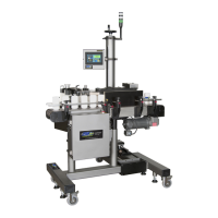
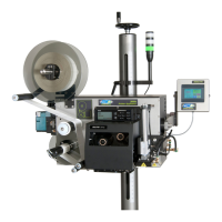
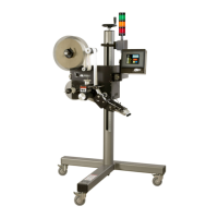
The 360a-CE applicator was tested as a merge with the product detect sensor and display attached.
Because of the many configurations and options that are available for this model, there was no way to
test all configurations. The only issue with the different noses will be machine safety. The integration of
an applicator into a product line may cause pinch points or other dangerous situations that will need
guarded. The responsibility for guarding lies with the integrator.
Safety Related Issues to Ensure Compliance
• End user is responsible for meeting the final protective ground requirements.
• The power inlet on the back of the applicator is the AC power disconnect. The end user is
responsible for determining and providing a supply disconnect for the system.
• Voltages greater than 60 volts may be present inside the applicator after a discharge time of 5
seconds.
• The end user must provide protection concerning power interruptions/restoration, if needed.
• The end user must provide earth ground fault current protection, if required.
• The end user will provide any guarding needed after integration of the applicator.
Emergency Stop Actuators
EN/ISO 13850:2015 Clause 4.3.2 requires that an emergency stop device shall be located at each operator
control station, except where the risk assessment indicates that this is not necessary.
Upon reviewing the machine with the manufacture, it was agreed that the risks posed by the labeling
machine itself are not sufficient as to require a dedicated emergency stop pushbutton at the HMI console.
An entanglement test was preformed between the Nip and Drive rollers, and it was found that no
significant pull was exerted on fabric, and that only a mild pinch was exerted on the fingers.
The main machine into which this machine is incorporated should have an emergency stop system that
will remove power and air to the 360a system, thus removing all power to its actuators.
Acoustic Emissions Data
A weighted emission sound pressure levels at workstations do not exceed 70 dB(A).
Measurement Locations:
M1 –In front of label spindle
M2 –Operator’s position when using the HMI
M3 –Rear of machine frame