DRIVE SYSTEM-IVT
37
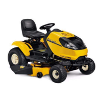
8a. Remove the hair and clevis pins.
See Figure 5B.25
8b. Slide the drive control links off of the input
levers
9. Remove the two screws that fasten the expan-
sion tank to the left side of the frame. See Figure
5B.26
NOTE: The seat frame plate was removed for a
clearer picture.
NOTE: Clamp off both of the lines going to the
expansion tank to help prevent loss of traction
fluid. Currently replacement traction fluid is not
available for purchase.
Figure 5B.25
Clevis pin
Hair pin clip
drive control link
Figure 5B.26
Expansion
tank
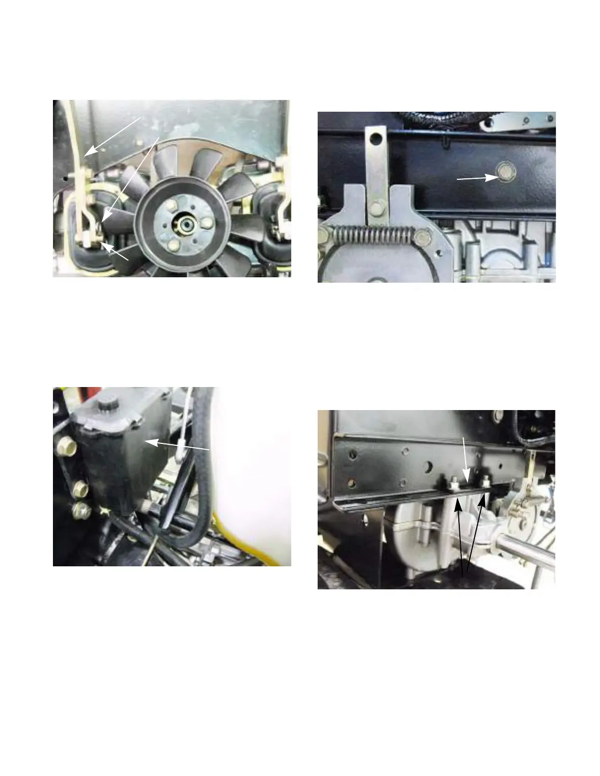
10. Remove front mounting screw on each side of
the tractor using a 1/2” wrench.
See Figure 5B.27
NOTE: Support the transmission to prevent it
from falling while the mounting bolts are
removed.
11. Remove the two bolts that fasten the transmis-
sion to the frame and the support plate on each
side of the tractor. See Figure 5B.28
12. Lower the transmission out of the tractor.
NOTE: Avoid spilling traction fluid while moving
the transmission. Currently replacement traction
fluid is not available for purchase.
Figure 5B.27
Front mounting
screw
Figure 5B.28
Support plate
Mounting bolts and nuts
 Loading...