STEERING-IVT
93
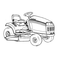
4. Remove the six remaining case screws using a
3/8” wrench. See Figure 6B.38.
5. Lift the upper housing off of the lower housing.
NOTE: There is no sealant between the two
housings. They should easily slip apart. If they
are stuck together, there are three pry points
cast into the housings that can be used to sepa-
rate the housings.
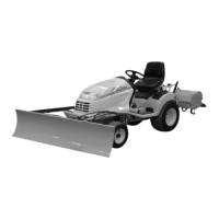
6. Remove the speed cam assemblies.
See Figure 6B.39.
Figure 6B.38
Remove
these
screws
Figure 6B.39
Speed cam assemblies
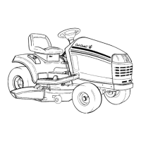
7. Separate the speed cam assemblies by driving
out the two roll pins using a 5/32” pin punch and
a hammer. See Figure 6B.40.
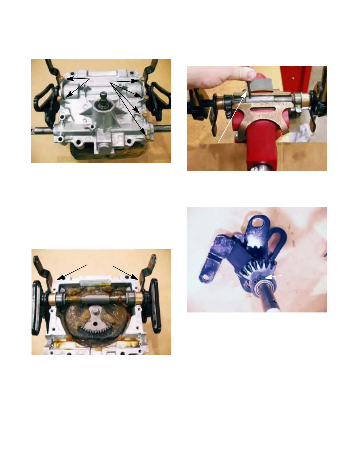
8. Separate the output bevel gear assembly by
removing the snap ring. See Figure 6B.41.
Figure 6B.40
5/32” pin punch
Figure 6B.41
Remove this
snap ring
 Loading...