CUH CUH CUH CUH CUH CUH CUH
CUH CUH CUH CUH CUH CUH CUH CUH CUH CUH CUH CUH CUH CUH CUH CUH CUH CUH CUH CUH CUH
CUH CUH CUH CUH CUH CUH CUH CUH CUH CUH CUH CUH CUH CUH CUH CUH CUH CUH CUH CUH CUH
CUH CUH CUH CUH CUH CUH CUH CUH CUH CUH CUH CUH CUH CUH CUH CUH CUH CUH CUH CUH CUH
CUH CUH CUH CUH CUH CUH CUH CUH CUH CUH CUH CUH CUH CUH CUH CUH CUH CUH CUH CUH CUH
CUH CUH CUH CUH CUH CUH CUH CUH CUH CUH CUH CUH CUH CUH CUH CUH CUH CUH CUH CUH CUH
CUH CUH CUH CUH CUH CUH CUH CUH CUH CUH CUH CUH CUH CUH CUH CUH CUH CUH CUH CUH CUH
CUH CUH CUH CUH CUH CUH CUH CUH CUH CUH CUH CUH CUH CUH CUH CUH CUH CUH CUH CUH CUH
CUH CUH CUH CUH CUH CUH CUH CUH CUH CUH CUH CUH CUH CUH CUH CUH CUH CUH CUH CUH CUH
20
T1
T1
T2
T2
5.4.3 Control Output Mode Description
5.4.4 Main Output Signal Control Function
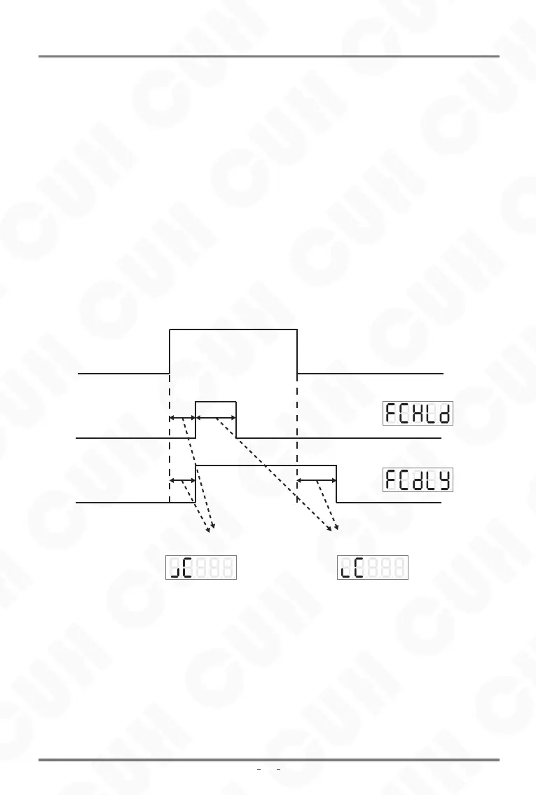
T1: Output signal rising edge delay
T2: Output signal falling edge delay
The signal output after the logic relationship selector
Hold mode output
Delay mode output
Customers can choose 2 control output modes: delay mode, hold mode.
Delay mode: It means that after the controller output drive signal changes from
valid to invalid, the control output turns off after a period of off delay time.
Hold mode: After the controller output drive signal becomes valid, the control
output remains on during the off-delay time, and turns off after the off-delay time
is exceeded.
The difference between the two modes is expressed in the form of a timing diagram
as follows, where the input signal is the signal output after the logic relationship
selector.
The main output signal control is similar to that of the control output. After selecting
three signal sources for logic relationship operation, the control signal is obtained
through on/off delay mode selection and logic direction control. The control signal is
logically with the on/off signal of the panel, than send to the power board to control
the main output.
The main output signal control wiring method, signal source and logic diagram can
refer to the control output function.
SDMC20-S
SDMC20_SMS-EN_2.01
Digital Single Phase Asynchronous Motor Controller
2023-11