CUH CUH CUH CUH CUH CUH CUH
CUH CUH CUH CUH CUH CUH CUH CUH CUH CUH CUH CUH CUH CUH CUH CUH CUH CUH CUH CUH CUH
CUH CUH CUH CUH CUH CUH CUH CUH CUH CUH CUH CUH CUH CUH CUH CUH CUH CUH CUH CUH CUH
CUH CUH CUH CUH CUH CUH CUH CUH CUH CUH CUH CUH CUH CUH CUH CUH CUH CUH CUH CUH CUH
CUH CUH CUH CUH CUH CUH CUH CUH CUH CUH CUH CUH CUH CUH CUH CUH CUH CUH CUH CUH CUH
CUH CUH CUH CUH CUH CUH CUH CUH CUH CUH CUH CUH CUH CUH CUH CUH CUH CUH CUH CUH CUH
CUH CUH CUH CUH CUH CUH CUH CUH CUH CUH CUH CUH CUH CUH CUH CUH CUH CUH CUH CUH CUH
CUH CUH CUH CUH CUH CUH CUH CUH CUH CUH CUH CUH CUH CUH CUH CUH CUH CUH CUH CUH CUH
CUH CUH CUH CUH CUH CUH CUH CUH CUH CUH CUH CUH CUH CUH CUH CUH CUH CUH CUH CUH CUH
26
PE
PE
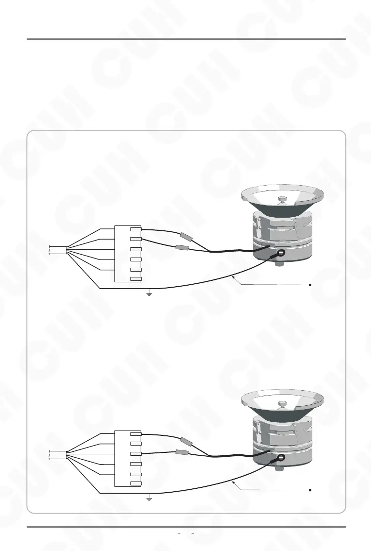
Disconnect the power supply and connect the red and black wires of the output
cable to the vibratory feeder.
If you previously opened the cover and adjusted the output wire from CW to CCW
position, connect the red wire and white wire of the output cable to the vibratory
feeder.
The output cable is connected to the CW position of the circuit board by default
Adjust the output cable to the CCW position of the circuit boardconnected
5.10 Control Vibratory Feeder Mode
red
red
brown
brown
green
green
black
black
white
white
Output Cable
Output Cable
yellow-green
yellow-green
Earth Wire
Earth Wire
(Yellow - Green Dual color Wire)
(Yellow - Green Dual color Wire)
The controller can be connected to the vibratory feeder, and the connection method
is as follows:
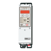
SDMC20-S
SDMC20_SMS-EN_2.01
Digital Single Phase Asynchronous Motor Controller
2023-11