G1 RO Parts Diagrams and Lists 85
Cat. No. 01021713
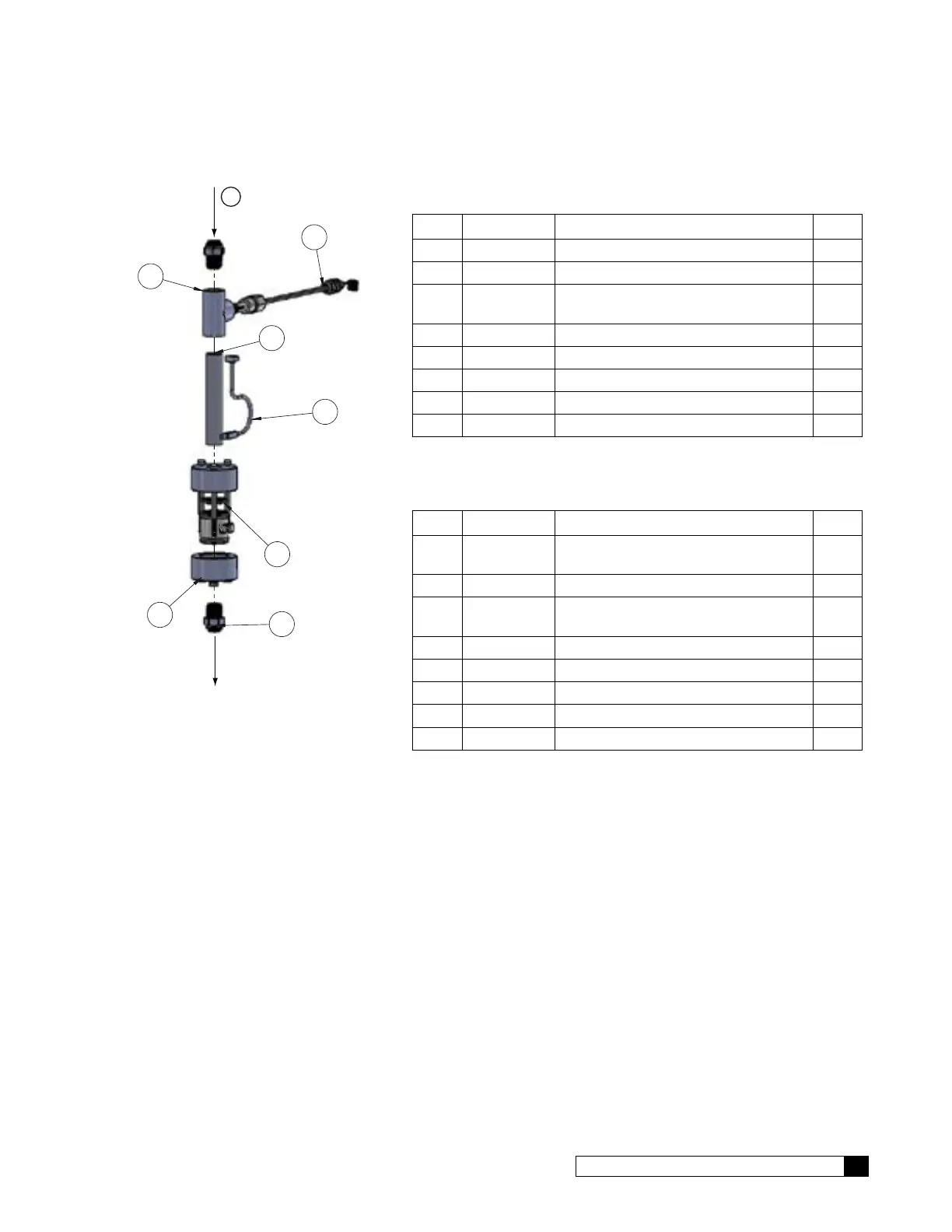
Product Assembly
11.53
REF.
NOTE DIRECTION OF
FLOW METER
4
2
1
3
5
6
7
Product from
Membrane Assy
Product Outlet
C
Figure 41. G1 Product Assembly.
For G1 2S, 3S, 4S, 2L, 3L, 4L
Item Part No. Description Qty
01024512 Assembly, Product Flow Meter, G1
1 — Nipple, 1/2"x5, PVC Sch. 80, TBE 1
2
01021033 Adapter Assembly, Flow Meter,
1/2" NPT
1
3 — Tee, 1/2", Threaded, PVC Sch. 80 1
4 — 1/2"-1/2" NPT Tube, Male Connector 2
5 01024516 Sensor, TDS, 24"L with 5 Pos Conn 1
6 01025827 Harness, Meter, 28" Long 1
7 01022706 Nozzle, Flow Meter 1
For G1 1F, 2F
Item Part No. Description Qty
01024520 Assembly, Product Flow Meter, G1-1F,
2F
1 — Nipple, 1/2"x5, PVC Sch. 80, TBE 1
2
01021033 Adapter Assembly, Flow Meter,
1/2” NPT
1
3 — Tee, 1/2", Threaded, PVC Sch. 80 1
4 — 1/2"-1/2" NPT Tube, Male Connector 2
5 01024516 Sensor, TDS, 24"L with 5 Pos Conn 1
6 01025827 Harness, Meter, 28" Long 1
7 — NOT USED
 Loading...