G1 RO Parts Diagrams and Lists 89
Cat. No. 01021713
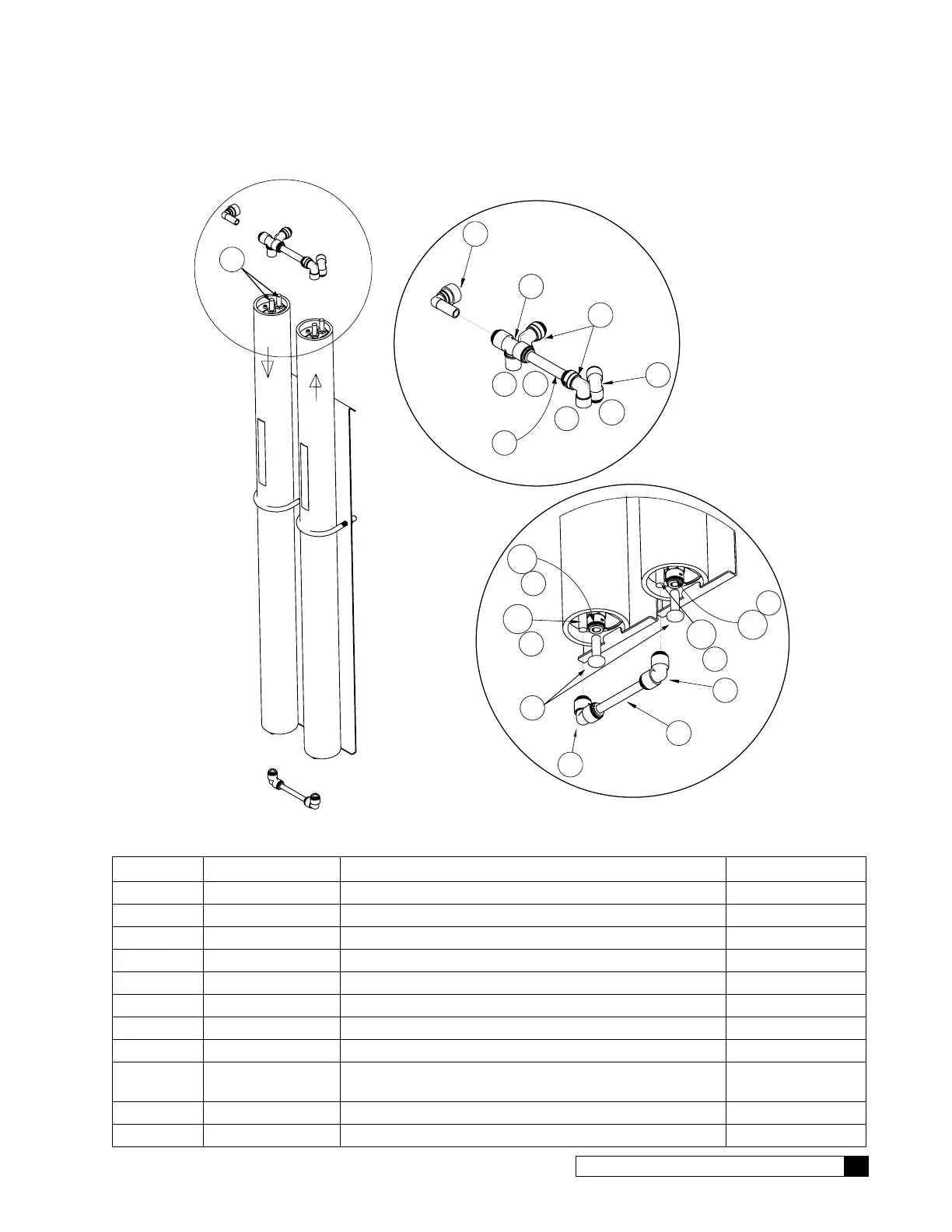
2S/2L Sub-Assembly
Bottom View
4
8
C
A
2
1
Note
orientation
of flow
A = to Feed Port
B = to Recirculating Assy
C = to Center Port (Product)
Top View
Used Only When
Mounting on
Floor Stand
3
1
B
A
1
4
7
C
C
6
FEED
PRODUCT
4
A
C
1
5
5
Figure 45. 2S/2L sub-assembly.
Item Part No. Description Quantity
01023412 Assembly, Membrane Housing, Single, 2.5"x21" (2S)
01023417 Assembly, Membrane Housing, Single, 2.5"x40" (2L)
01023907 Kit, Tube and Fittings, 2S, 2L (includes items 1–8)
1 — Elbow, Union, 3/8 Tube, PI, Polypropylene 3 EA
2 — Tube, 3/8", cut length 3" 1 EA
3 — Tube, 1/2", Length 3.5" 1 EA
4 — Stem Adapter, 1/4Tx3/8 Stem, Polypropylene 6 EA
5 — Elbow, Union, Reducing, 1/2 x 3/8, PI, Polypropylene 2 EA
6
— Tee, Union, Reducing, 1/2 Ends, 3/8 Branch, PI,
Polypropylene
1 EA
7 — Elbow,1/2 Stem x 1/2T,PI 1 EA
8 — Plug, 1/4" NPT, PVC Sch 80 2 EA
 Loading...