68
69
force. If you can fully close the quick release without wrapping
lever does not leave a clear imprint in the palm of your hand,
6. If the lever cannot be pushed all the way to a position parallel to
the fork blade, return the lever to the OPEN position. Then turn the
tension adjusting nut counterclockwise one-quarter turn and try
tightening the lever again.
7. Re-engagethebraketorestorecorrectbrakepad-to-rimclearance;
spin the wheel to make sure that it is centered in the frame and
clearsthebrakepads;thensqueezethebrakeleverandmakesure
that the brakes are operating correctly.
Springs
a
Tension
adjusting nut
b
open
closed
c
Installing a quick release front wheel
In a quick release system, the wheel hub is clamped in place by the force of the quick release cam pushing
against one dropout and pulling the tension adjusting nut, by way of the skewer, against the other dropout.
The amount of clamping force is controlled by the tension adjusting nut. Turning the tension adjusting nut
clockwisewhilekeepingthecamleverfromrotatingincreasesclampingforce;turningitcounterclockwise
while keeping the cam lever from rotating reduces clamping force. Less than half a turn of the tension
adjusting nut can make the difference between safe clamping force and unsafe clamping force.
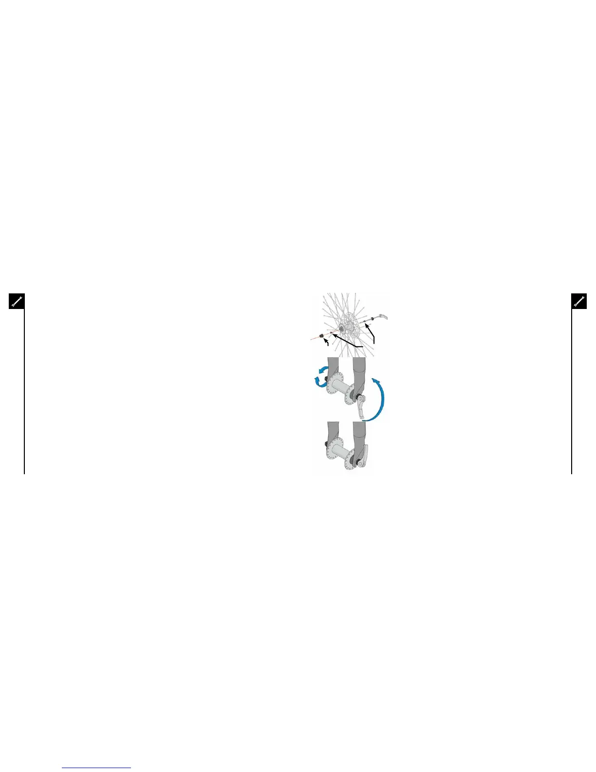
1. Remove the tension adjusting nut and one of the small springs, then slide the quick release skewer through
the hub. If your bicycle has a disc brake, insert the skewer starting on the side with the brake rotor. Replace
thespringandtensionadjustingnut(figa).
2. If your bicycle has rim brakes, disengage them to increase the clearance between the tire and brake pads.
3. Installthewheelintothedropouts,makingsurethequickreleaseleverisontheleftsideofthebicycle.
4. HoldingthequickreleaseleverintheOPENpositionwithonehand,tightenthetensionadjustingnutwith
yourotherhanduntilitisfingertightagainsttheforkdropout.
5. Whilepushingthewheelfirmlytothetopoftheslotsintheforkdropouts,andatthesametimecenteringthe
wheelriminthefork,movethequick-releaseleverupwardsandswingitintotheCLOSEDposition(figb&c)
The lever should now be parallel to the fork blade and curved toward the wheel. To apply enough clamping
force,youshouldhavetowrapyourfingersaroundtheforkbladeforleverage,andthelevershouldleavea
clear imprint in the palm of your hand.