6
Curtis PMC 1204/1205 Manual
OTHER HARDWARE
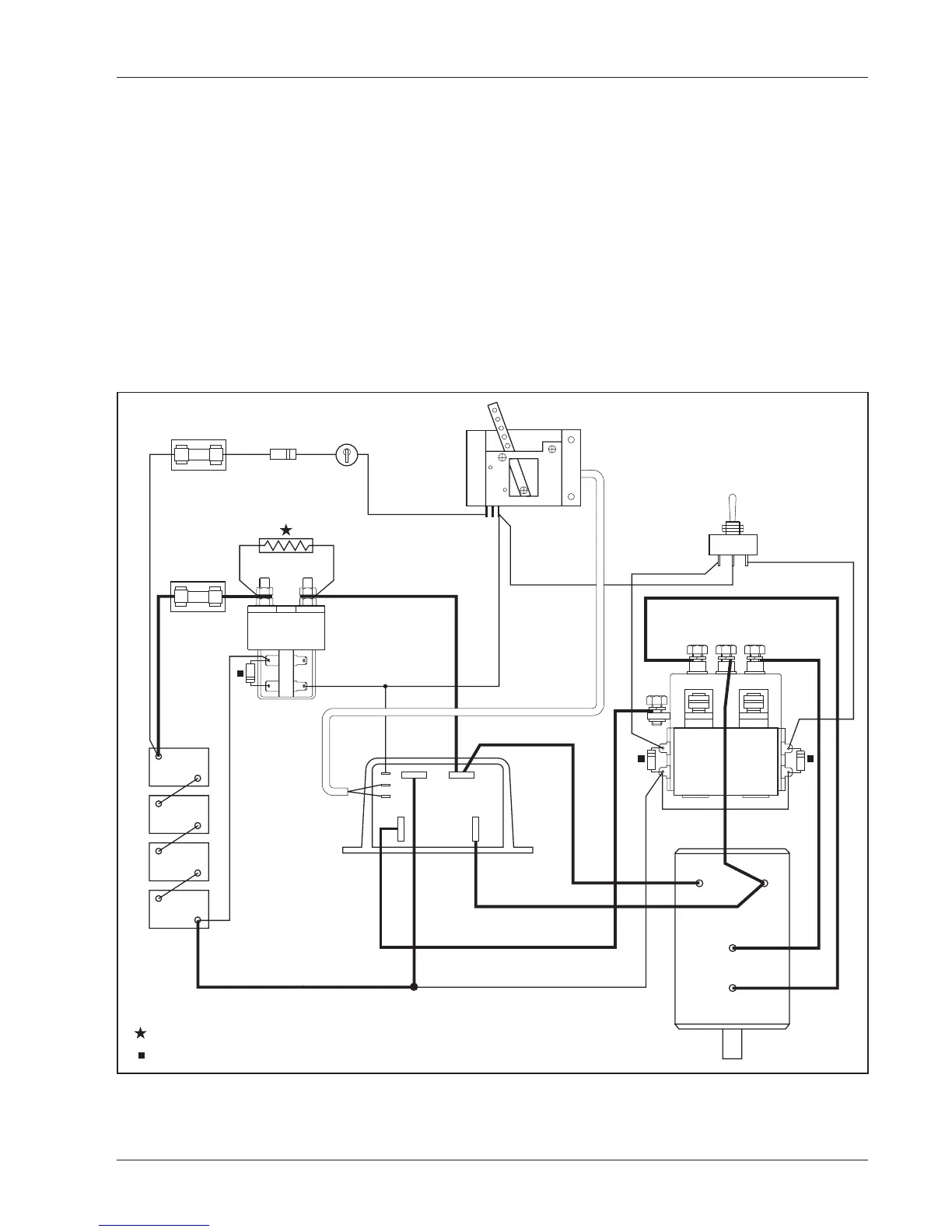
The recommended hardware for a typical 1204/1205 controller installa-
tion is shown in Figure 5.
Contactors should be mounted in a clean, dry location. If such a
location is unavailable, a cover should be used to deflect dirt and water
splash.
The precharge resistor connected to the main contactor, and the coil
suppression diodes connected to the main contactor and to the forward/
reverse contactors, are somewhat delicate components. Care should be
taken to prevent damage to them during installation.
CONTROL
WIRING
FUSE
POWER
WIRING
FUSE
POLARITY
PROTECTION
DIODE
KEYSWITCH
POTBOX
FORWARD/REVERSE SWITCH
(SPDT, center off)
FR
F/R CHANGEOVER CONTACTOR
(Albright DC182 shown)
MAIN
CONTACTOR
(Albright
SW180
shown)
A1
A2
S1
S2
SERIES
MOTOR
BATTERY
A2M-
B- B+
B-
B+
PRECHARGE RESISTOR, such as Curtis PMC p/n MP-2
COIL SUPPRESSION DIODE, such as Curtis PMC p/n MP-1
(250Ω, 5W)
N.C.
COM.
FWD REV
Fig. 5 Typical installation,
Curtis PMC 1204/1205 controller.
HARDWARE INSTALLATION

 Loading...


