17
Curtis PMC 1204/1205 Manual
WIRING: PM MOTORS
Wiring for controllers in vehicles with permanent magnet motors is the
same as in those with series motors, except for the forward/reverse circuit.
PM motors have only two terminals: the armature brushes. The magnetic
field is provided by the permanent magnets and cannot be reversed;
instead, the motor is reversed by interchanging the armature leads.
The PM motor must be connected, via the forward/reverse circuitry,
to the controller’s B+ and M- bus bars. If your controller is designed for
use with either series or PM motors, it will have an A2 bus bar which you
should leave unconnected. If your controller is designed for use only with
PM motors, it will have no A2 bus bar.
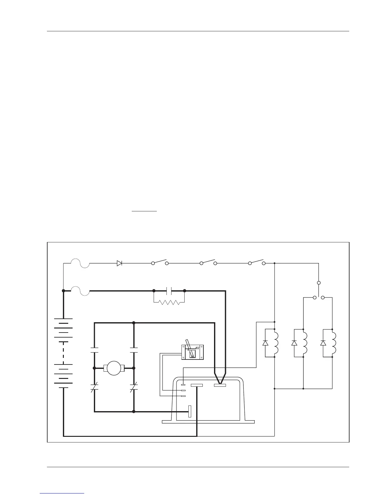
Basic PM motor wiring — using two single-pole, double-throw
(2×SPDT) contactors — is shown in Figure 15. Note that when the
forward/reverse switch is in the neutral position, neither of the direction
contactors is operated and the motor is shorted. This will produce sudden
braking if neutral is selected while the vehicle is moving, or if the motor
is reversed while the vehicle is moving. The motor acts as a generator, and
will effectively be shorted out by the freewheel diode inside the controller.
The faster the vehicle is moving when the motor is shorted out, the more
Fig. 15 Basic wiring for use with PM motors.
WIRING
+
–
FORWARD
REVERSE
MAIN
FR
B- B+
M-
F
R
F
R
POTBOX
MAIN
KEYSWITCH INTERLOCKS
PEDAL
MICROSWITCH
CONTROL WIRING
FUSE
POLARITY
PROTECTION
DIODE
PRECHARGE RESISTOR
(250 Ω, 5 W)
POWER WIRING
FUSE
PM

 Loading...


