33
Curtis PMC 1204/1205 Manual
For controllers with other input options, use whatever kind of
potbox is used on the vehicle.
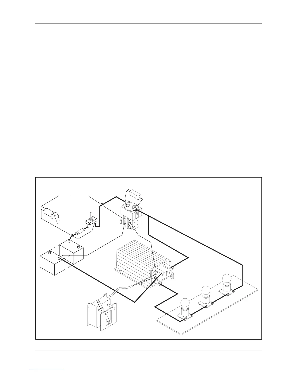
3. a POWER SWITCH to disconnect all power from the test
setup.
4. a MAIN CONTACTOR with a 250 ohm, 5 watt resistor
across its high-power contacts and a KEYSWITCH to turn it on
and off.
5. a TEST LOAD consisting of incandescent light bulbs wired
in series to get the same voltage as your power supply. (For
example, with a 36 volt battery, use three 12 volt bulbs.)
6. a general purpose VOLT OHMMETER or DIGITAL
VOLTMETER.
TROUBLESHOOTING & BENCH TESTING
Fig. 20 Setup for bench testing.
10A FUSE
5W, 250
Ω
RESISTOR
TEST LOAD
(to match battery voltage)
12 V
12 V
12 V
POTBOX
(to match your controller’s
throttle input)
POWER SUPPLY
(to match your controller)
KEYSWITCH
POWER
SWITCH
MAIN
CONTACTOR
+
-

 Loading...


