11
Curtis PMC 1204/1205 Manual
WIRING
turn off the main contactor and the forward/reverse contactors. This will
act as a safety feature by removing power from the motor control system
when the keyswitch is turned off.
Interlocks (seat switches, battery charger interlocks, etc.) should be
wired in series so that they turn off the controller KSI and the contactors.
Forward/Reverse Wiring (with standard power wiring)
These forward/reverse wiring schemes assume the standard power wiring
(shown by the heavy lines in Figure 6). Some vehicles, especially those
previously using older, resistor-type controllers, may reverse the motor
armature rather than the field winding. Be careful if you are replacing this
type of controller. When using the Curtis PMC controller it is essential
that the field be reversed and that the armature be connected directly
to the controller’s B+ and A2 terminals, because the plug diode inside
is connected to these terminals.
Plug braking
The standard forward/reverse control wiring (shown by the light lines in
Figure 6) provides plug braking. The forward/reverse switch should be in
the positive feed to the contactor coils, so that they can be turned off by
the keyswitch, interlocks, and pedal microswitch. The coil of one contactor
or the other is energized to select the direction desired.
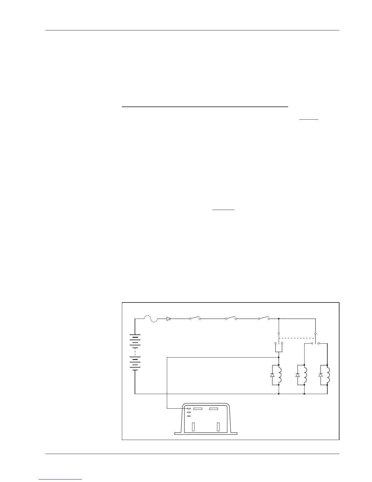
Freewheeling (wiring to inhibit plug braking)
If your controller has the HPD option, this feature can be used to inhibit
plug braking by briefly turning off the controller’s KSI when the forward/
reverse switch goes through neutral. As shown in Figure 7, another set of
Fig. 7 Control wiring
for inhibiting plug
braking, in order to
allow freewheeling.
FORWARD
REVERSE
MAIN
KEYSWITCH
INTERLOCKS
PEDAL
MICROSWITCH
FUSE
POLARITY
PROTECTION
DIODE
B-
B+
M-
A2
F/R SWITCH
(DPDT, center off)
+
–

 Loading...


