10
Curtis PMC 1204/1205 Manual
WIRING
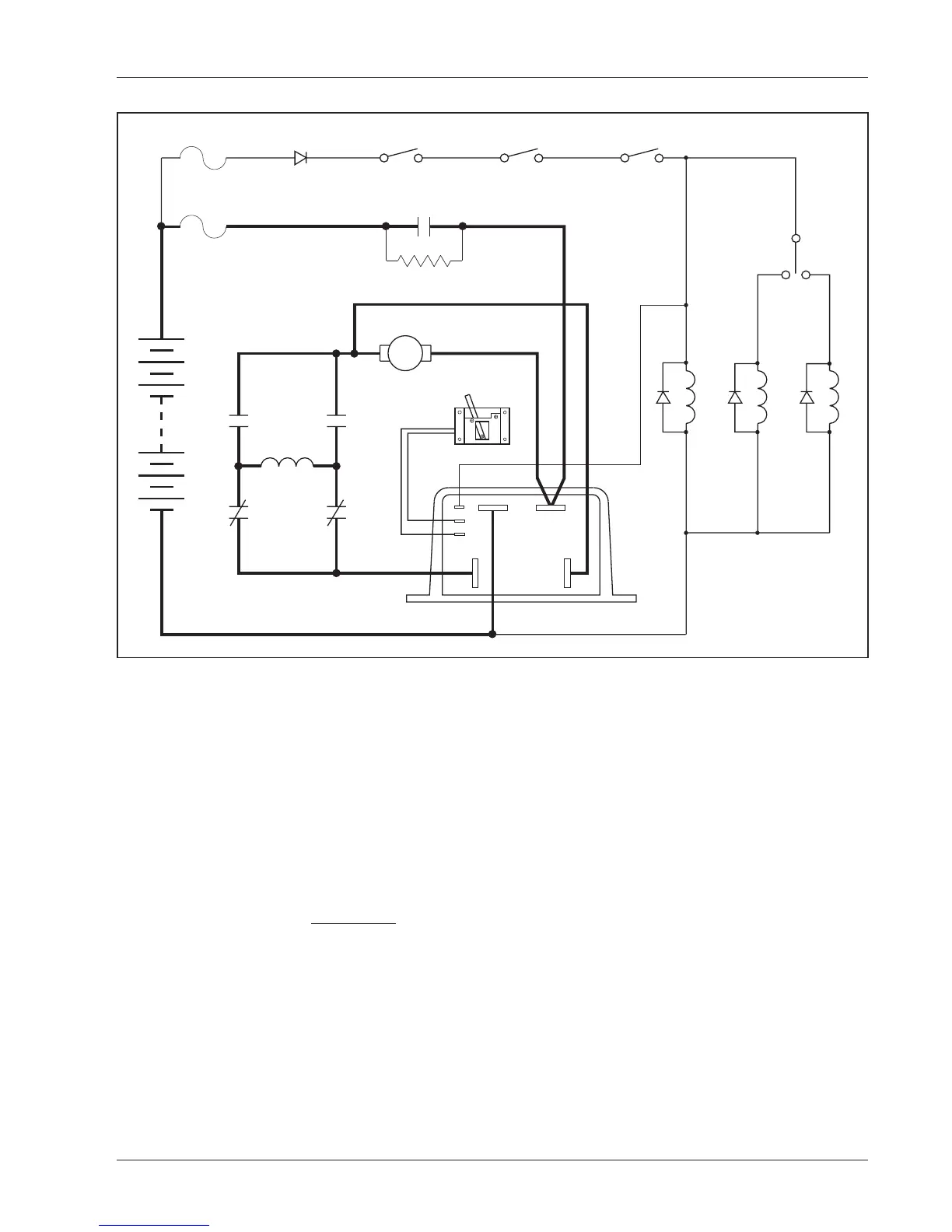
Fig. 6 Basic wiring configuration,
Curtis PMC 1204/1205 controller.
WIRING: SERIES MOTORS
Figure 6 is a schematic of the configuration shown in Figure 5. Wired this
way, the vehicle will plug brake if the direction is changed with the vehicle
moving and the throttle applied. Reversing is accomplished via two single-
pole, double-throw (2×SPDT) contactors. Coil suppression diodes should
be used on the main and forward/reverse contactors.
KSI Wiring
The keyswitch input (KSI) circuit includes input from the keyswitch and
from the various interlocks. The controller KSI is used to turn the
controller on and off. KSI is turned on by connecting it to battery B+. Any
positive voltage greater than about 8 volts will turn on the controller, but
usually the full vehicle battery voltage is used. KSI draws only a very small
current (a few mA).
In its simplest form, KSI is operated by a keyswitch that turns the
vehicle off and prevents unauthorized use. The keyswitch should also
+
–
FORWARD
REVERSE
MAIN
FR
B- B+
M- A2
S2
A2
S1
A1
F
R
F
R
POTBOX
MAIN
KEYSWITCH INTERLOCKS
PEDAL
MICROSWITCH
CONTROL WIRING
FUSE
POLARITY
PROTECTION
DIODE
PRECHARGE RESISTOR
(250 Ω, 5 W)
POWER WIRING
FUSE

 Loading...


